Supercharge Your Innovation With Domain-Expert AI Agents!

Device for locating a first aerospace component relative to a second aerospace component

a technology for aerospace components and components, applied in the direction of material gluing, turning apparatuses, key-type connections, etc., can solve the problems of structural failure of the joint and/or the components, fuel leakage or overall breakdown of the aircraft, and metal mechanical fixtures

Inactive Publication Date: 2011-12-08
AIRBUS OPERATIONS LTD
View PDF16 Cites 11 Cited by
  • Summary
  • Abstract
  • Description
  • Claims
  • Application Information

AI Technical Summary

Benefits of technology

The present invention provides a device and method for locating a first aerospace component relative to a second aerospace component. The device includes a bladder with a flexible membrane that defines a fluid receiving space between the components. When a hardenable hydraulic fluid is injected into the bladder, the membrane is urged to deform and locate the components relative to each other. The device also includes an inlet and an outlet for the fluid, and a bonding means to secure the membrane to the components. The invention allows for precise positioning of aerospace components during assembly, reducing assembly time and improving assembly accuracy.

Problems solved by technology

Although such conventional fixings form a secure joint to fixedly locate adjacent surfaces, they are known to have a number of disadvantages when used in an aerospace assembly.
Conventional fixings are known to cause metal fatigue and localised stress concentrations of the area proximal to each pre-formed hole, which may lead to a structural failure of the joint and / or the components, and cause, for example, fuel leakage or overall breakdown of the aircraft.
Furthermore, mechanical fixtures made of metal may in particular pose a problem to aircrafts formed from carbon fibre composites if the aircraft was to be struck by lightening, as this may cause electrical failure or ignition of the fuel held in the fuel tank.
One issue with components formed from carbon fibre composite materials is that although one surface is generally produced to an exact tolerance, the opposing surface is generally of low tolerance, typically up to + / −4%, depending on the process used.
With conventional fixings it is not possible for these inevitable manufacturing tolerances to be taken up is during assembly, and so it is necessary to modify or shim components to obtain the exact tolerances needed to ensure the desired joint, which is a complex and time-consuming process.
Irrespective of the manufacturing technique of aircrafts, there will be gaps and voids between the structural components as they are assembled.
Consequently, the manufacturing of aircraft is time consuming and usually results in wastage and a high scrap rate such that it is difficult to manufacture and assembly high volumes of aircrafts and aeronautical components, whilst also meeting the requirements for close tolerance, which is particularly difficult when utilising carbon fibre composites.

Method used


Image

  • Device for locating a first aerospace component relative to a second aerospace component
  • Device for locating a first aerospace component relative to a second aerospace component
  • Device for locating a first aerospace component relative to a second aerospace component

Examples


Embodiment Construction

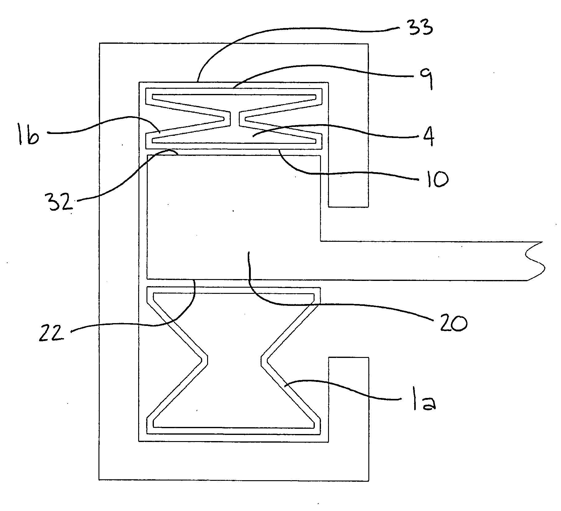
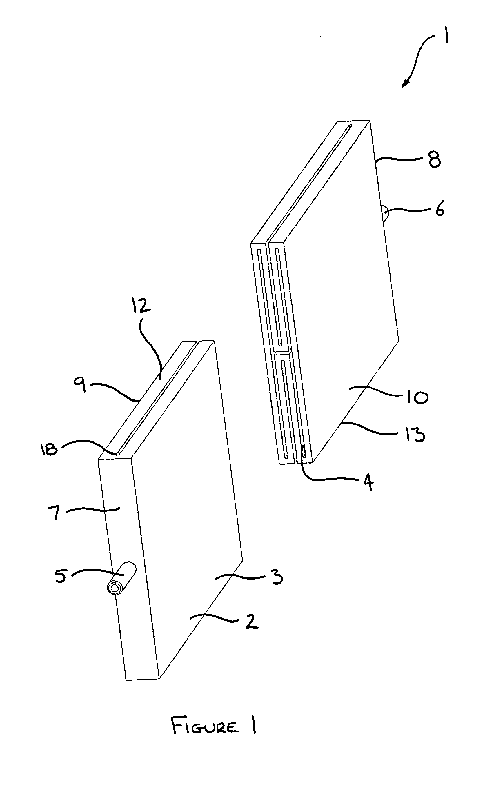
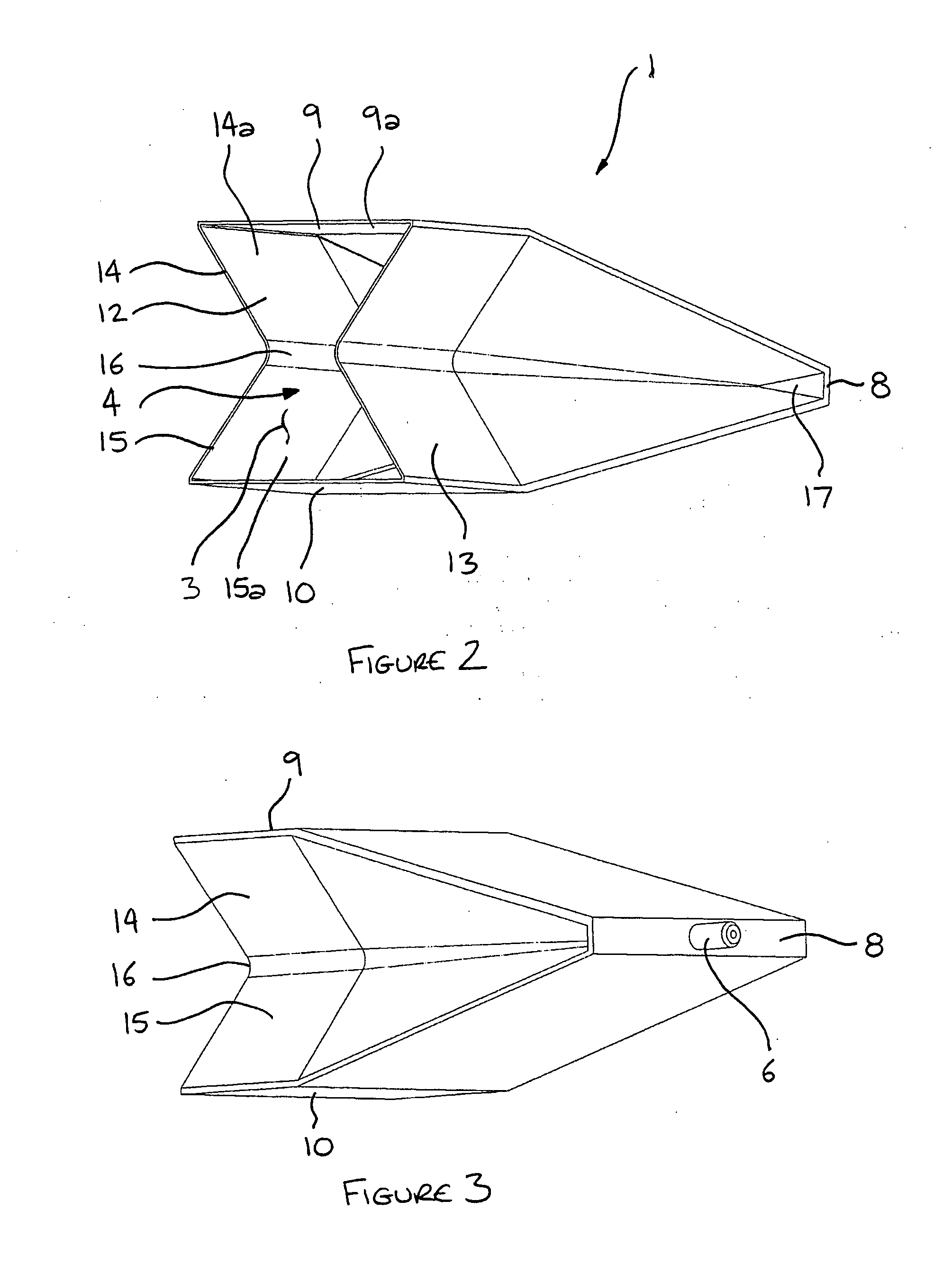
[0039]Referring now to the accompanying drawings, a device 1 for locating a first aerospace component relative to a second aerospace component is shown in FIGS. 1 to 5 comprising a bladder 2 formed from a flexible, incompressible membrane 3, which encloses and defines a fluid receiving space 4. An inlet 5 and an outlet 6 communicate with the fluid receiving space 4 at opposing ends of the bladder 2. Prior to use, as seen in FIG. 1, the device 1 is in an unexpanded state and is generally elongate and cuboidal in shape, although the device is not limited as such, as will be explained hereinafter. The bladder 2 has a front wall 7 and a rear wall 8 at opposing ends of the bladder 2, an upper and a lower wall 9, 10 and two sidewalls 12,13, each extending between the upper and lower walls 9,10. The inlet 5 extends through the front wall 7 to communicate with the fluid receiving space 4 and the outlet 6 extends through the rear wall 8 to communicate with the fluid receiving space 4.

[0040]W...


PUM

PropertyMeasurementUnit
flexibleaaaaaaaaaa
pressureaaaaaaaaaa
stress concentrationsaaaaaaaaaa

Abstract

A device for locating a first aerospace component relative to a second aerospace component, comprising a bladder with a flexible membrane which defines a fluid receiving space such that, when a hardenable hydraulic fluid is injected into the bladder, said membrane is urged to deform into abutment with said first and second aerospace components to locate said components relative to each other when the hydraulic fluid hardens.

Description

INTRODUCTION[0001]The present invention relates to a device for locating aerospace components relative to each other. Particularly, but not exclusively, the invention relates to a device for connecting, locating, driving, clamping, locking or shimming a first aerospace component relative to a second aerospace component. Other aspects of the present invention relate to a joint comprising first and second components located relative to each other by such a device, and a method of locating a first aerospace component relative to a second aerospace component.BACKGROUND[0002]Aircraft are assembled from a number of separate assemblies which are fixedly mounted to each other during assembly of the aircraft. Such an assembly includes wing boxes, leading and trailing edges of a wing, horizontal tail planes (HTPs), Vertical Tail Planes (VTPs) and the fuselage, which are themselves formed from a number of discrete components including spars, ribs, skin, gunnels, compression struts, and stringe...

Claims


Application Information

Patent Timeline
Patent Type & Authority Applications(United States)
IPC IPC(8): F16B11/00B29C45/14
CPCB29C45/1418B29L2031/3076Y10T403/47F16B3/005F16B11/006B29L2031/727
Inventor PARKER, SIMON JOHN
Owner AIRBUS OPERATIONS LTD
Features
  • R&D
  • Intellectual Property
  • Life Sciences
  • Materials
  • Tech Scout
  • Unparalleled Data Quality
  • Higher Quality Content
  • 60% Fewer Hallucinations
Learn More