Microfluidic device

Inactive Publication Date: 2011-12-08
ACAD SINIC
View PDF6 Cites 16 Cited by
  • Summary
  • Abstract
  • Description
  • Claims
  • Application Information

AI Technical Summary

Benefits of technology

[0007]It is now discovered that a monolithic sandwiched micropost array can be fabricated without using a bonding step. The obtained sandwiched micropost array (SMA) chip has internal channel that allows fluid to flow through a

Problems solved by technology

If one of the three layers is not smooth, the bonding fails and l

Method used


Image

  • Microfluidic device
  • Microfluidic device
  • Microfluidic device

Examples


example

Materials and Methods

[0036]Monolithic Internal Micro Pillar (MIPi) Chip

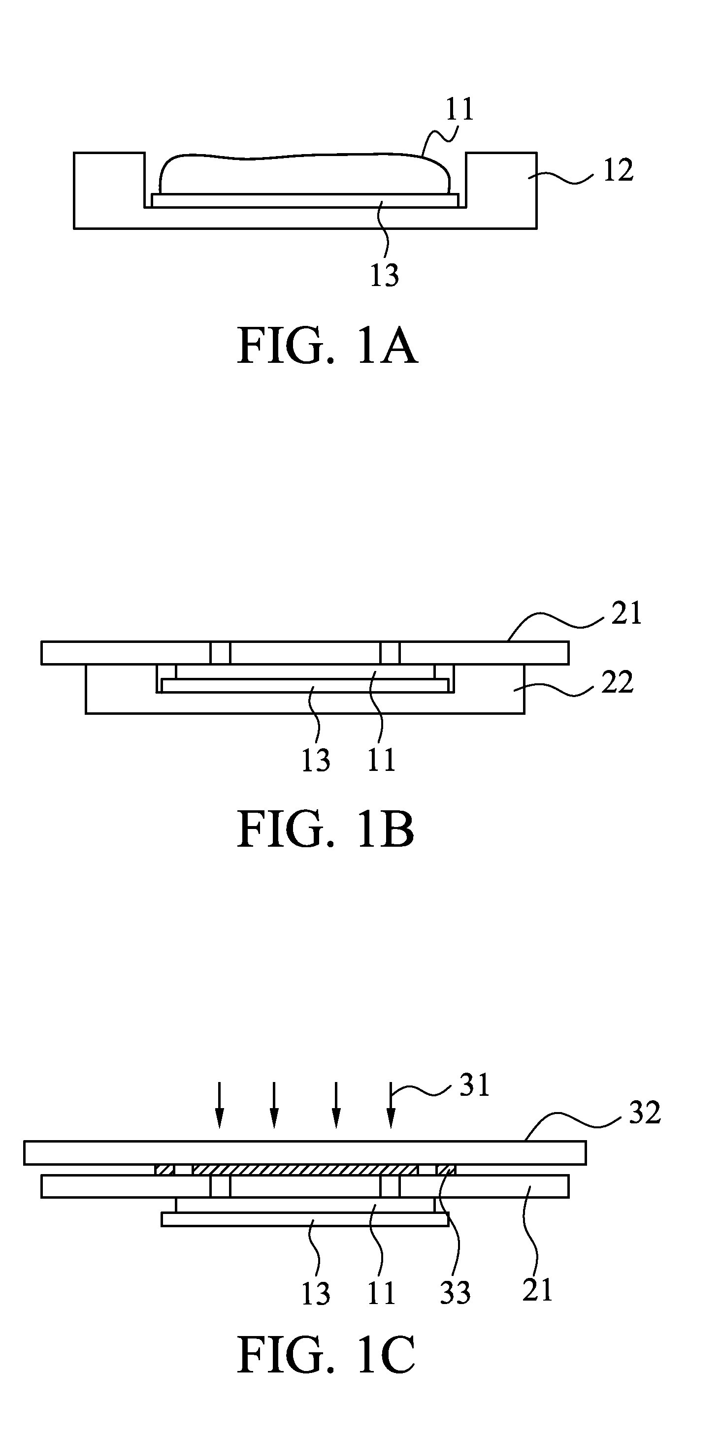
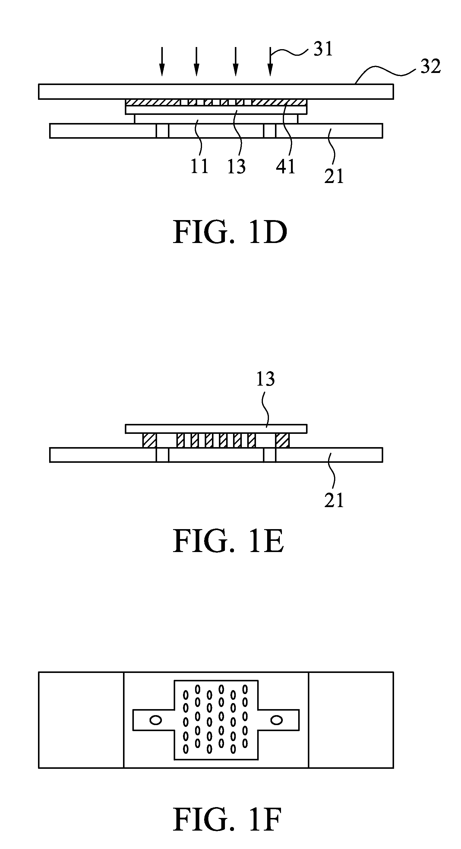
[0037]A MIPi chip was fabricated using a procedure as follows. One piece of cover glass and one piece of glass slide were first cleaned by isopropanol (IPA) and then immersed in 2N sulfuric acid (H2SO4) for 10 seconds. The substrates were then rinsed by de-ionized water and dried by nitrogen gas. The SU-8 photoresist (11) (MicroChem, 2015) was then dispensed on the cover glass (13) by a pipette (FIG. 1A). The cover glass (13) was put on a fixture (12) which has a groove of predetermined depth (FIG. 1A). A scraper was used to remove excess SU-8 so that an SU-8 layer with thickness of 210 μm was obtained. The depth of the groove can be adjusted to control the SU-8 thickness. Comparing to spin coating, this scrape coating method consumes less photoresist. The cover glass was then put on a hot plate for soft baking at 65° C. for six minutes. The resist-coated cover glass (13) was then put on a second fixture (22) (FI...


PUM


Abstract

A novel approach for fabricating Monolithic Internal micro Pillars (MIPi) made of SU-8 photoresist is described. A microfluidic chip with the internal pillars (a MIPi chip) was used for cell capturing study. The surface of MIPi was coated with specific antibody and then used for capturing cells by affinity binding. An antibody, anti-EGFR, which has high affinity to lung cancer cells, CL1-5, was coated on the micro pillars. The coated MIPi chip specifically captured the cancer cells that were pumped through the MIPi chip. Simulation and experiment was carried out to compare the effect of different geometry of the micro pillars on the cell capturing rate.

Description

CROSS REFERENCE TO RELATED APPLICATIONS[0001]This application claims the benefit of U.S. Provisional Application No. 61 / 352,431, filed Jun. 8, 2010.BACKGROUND OF THE INVENTION[0002]A microfluidic device often includes microstructures inside a microchamber. The microstructure can be of diverse function such as mixing, cell capturing, optical wave guiding, etc. Traditionally, structures inside a microchamber are fabricated by bonding multiple layers together. For example, a sandwiched structure has three layers, the bottom layer, the internal structure layer, and the cover layer. These three layers need to be bonded together so that the sandwiched structure can be fabricated. If one of the three layers is not smooth, the bonding fails and leakage occurs. For the conventional three-layered microfluidic device, alignment is often needed when bonding multiple layers that have patterns.[0003]Cell capturing plays an important role in medical analyses and has been receiving intensive attent...

Claims


Application Information

Patent Timeline
IPC IPC(8): C40B30/04C40B99/00C40B60/12
CPCB01L3/5027B01L2300/0636G01N33/54366B01L2400/086B01L2300/0877
Inventor CHENG, JI-YENCHANG, JOEL CHIA-YEHYANG, CHING-WEN
Owner ACAD SINIC
Why Eureka
Try Eureka