Method for Fabricating a Micromirror

a micromirror and mirror technology, applied in the field of microscanners, can solve the problems of large actuation power, small reflection angle of conventional microscanners, and complex fabrication procedures of conventional microscanners, and achieve the effects of low manufacturing cost, high actuation power, and high actuation power

Inactive Publication Date: 2011-12-15
ZHANG XIAOJING +3
View PDF2 Cites 10 Cited by
  • Summary
  • Abstract
  • Description
  • Claims
  • Application Information

AI Technical Summary

Problems solved by technology

However, conventional microscanners have small reflection angle and high actuation power.
In addition, conventional microscanners require complex fabrication procedures that are not compatible with standard silicon fabrication techniques used in the industry.

Method used


Image

  • Method for Fabricating a Micromirror
  • Method for Fabricating a Micromirror
  • Method for Fabricating a Micromirror

Examples


Embodiment Construction

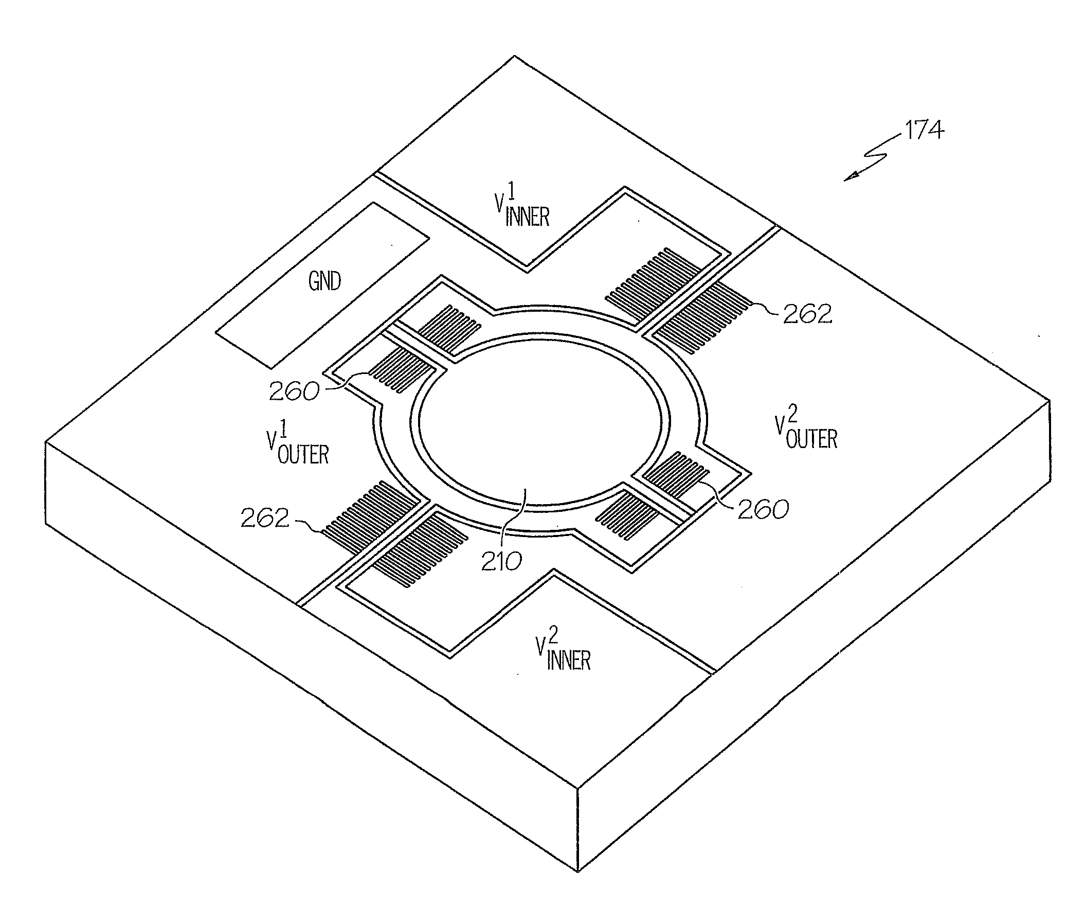
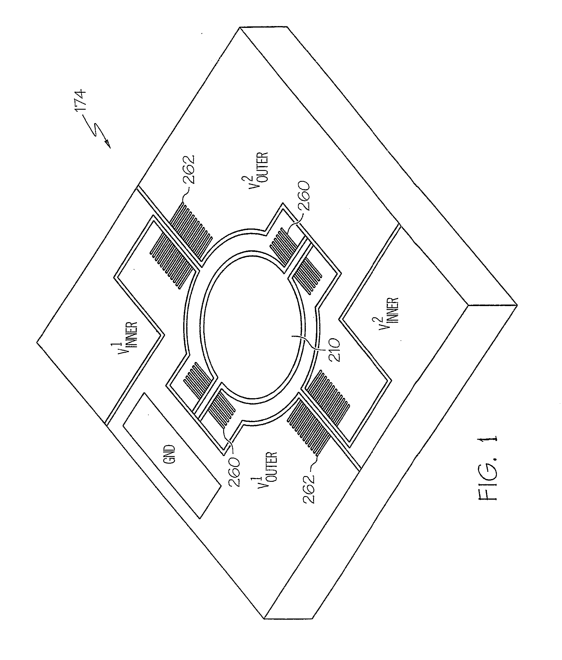
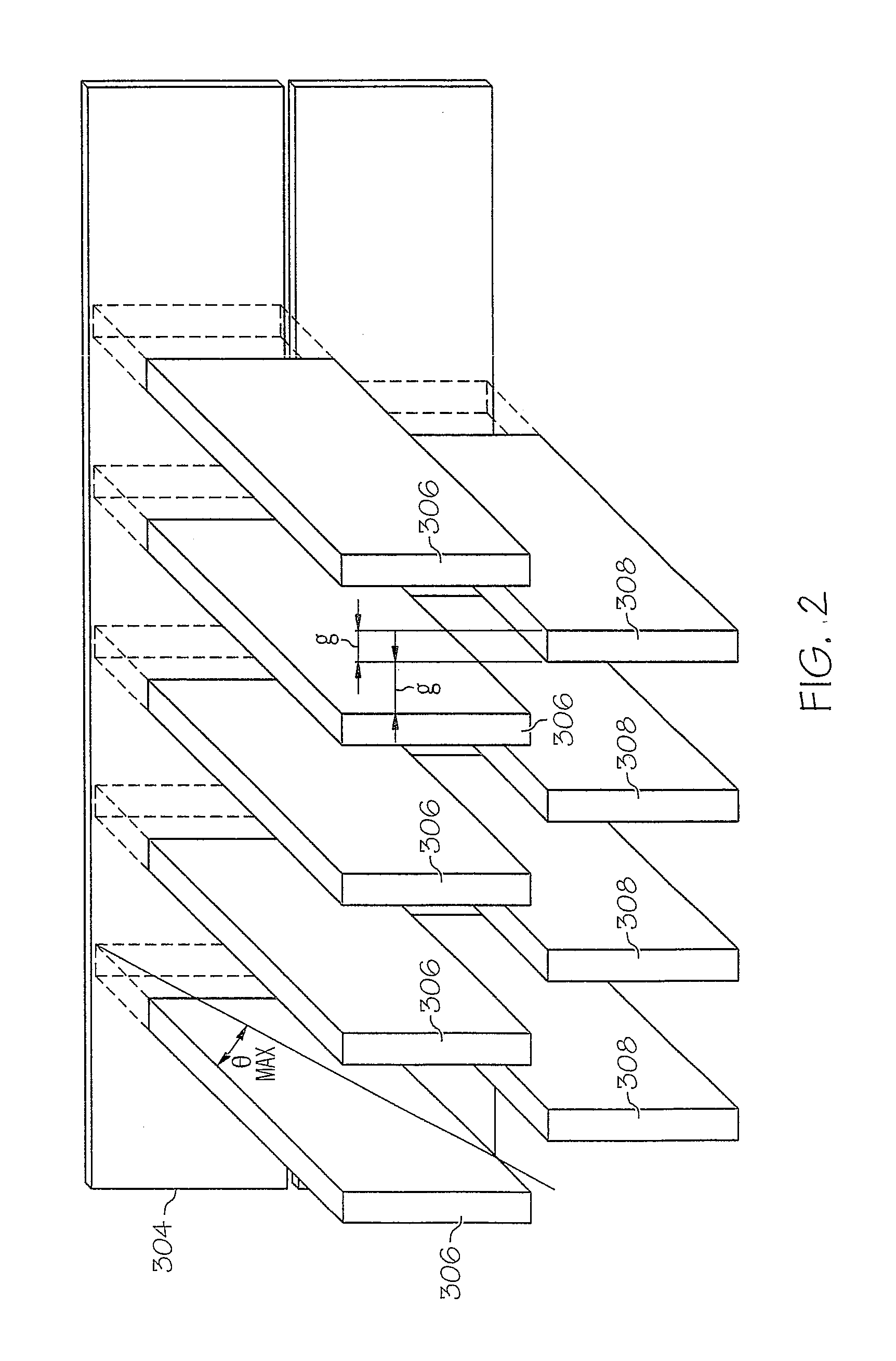
[0013]Referring now to the drawings and in particular to FIG. 1, there is depicted a diagram of a micromirror (or microscanner), in accordance with a preferred embodiment of the present invention. As shown, a micromirror 174 has two axes, and electrostatic vertical combdrives can be utilized to provide fast, high-torque rotary actuation about the two axes of micromirror 174. For example, two sets of staggered vertical combdrive actuators 260, 262 can be utilized to rotate rotatable minor 210 along each of the two axes. The movements of combdrive actuators 260, 262 can be controlled by the application of appropriate electrical biases via pads V1inner, V1outer, V2inner, V2outer and Ground. Combdrive actuators 260, 262 include rotor and stator comb fingers. The thickness and spacing between rotor and stator comb fingers are preferably fixed at approximately 8 μm.

[0014]The performance of micromirror 174 is characterized by its response to various electrical signal inputs. For example, o...


PUM

PropertyMeasurementUnit
thicknessaaaaaaaaaa
widthaaaaaaaaaa
widthaaaaaaaaaa

Abstract

A method for fabricating a micromirror is disclosed. A set of coarse features is formed in a low-temperature oxide (LTO) layer deposited on a front side of a wafer. A set of fine features is then formed in a photosensitive material layer deposited on top of the LTO layer. After removing a portion of the LTO layer to align the width of the coarse features with the width of the fine features, the first silicon dioxide layer and the first and second silicon device layers are etched to form stator comb fingers and rotor comb fingers accordingly. Finally, a portion of the substrate on a back side of the wafer is removed, and the silicon dioxide layers are removed from the front and back sides of the wafer to form a rotatable mirror.

Description

PRIORITY CLAIM[0001]The present application is a continuation-in-part of U.S. Non-provisional application Ser. No. 12 / 193,501, filed on Aug. 18, 2008, published on Feb. 10, 2010 under Pub. No. US 2010 / 00039687, which claims priority to U.S. Provisional Application No. 60 / 965,417, filed on Aug. 20, 2007, the contents of which are incorporated herein by reference.BACKGROUND OF THE INVENTION[0002]1. Technical Field[0003]The present invention relates to microscanners in general, and, in particular, to a method for fabricating a micromirror.[0004]2. Description of Related Art[0005]Microscanners are essential components for the miniaturization of optical diagnostic equipments such as endoscopes. For example, silicon-based microscanners have been integrated into confocal and other instruments for providing images. However, conventional microscanners have small reflection angle and high actuation power. In addition, conventional microscanners require complex fabrication procedures that are ...

Claims


Application Information

Patent Timeline
Patent Type & Authority Applications(United States)
IPC IPC(8): C23F1/00
CPCB29D11/00596B81B2201/042G02B26/0841B81C1/00626G02B26/0833B81B2203/0136
Inventor ZHANG, XIAOJINGWANG, YOUMINSHEN, TINGKUMAR, KARTHIK
Owner ZHANG XIAOJING
Why Eureka
Try Eureka