
System and Method for Vibration Control in a Rotorcraft Using an Adaptive Reference Model Algorithm

a reference model and rotorcraft technology, applied in mechanical equipment, instruments, transportation and packaging, etc., can solve problems such as pilot fatigue, flight control problems, and aircraft such as rotorcraft, and achieve the effects of improving flight control efficiency, material fatigue, and maintenance costs

Active Publication Date: 2011-12-15
TEXTRON INNOVATIONS
View PDF2 Cites 16 Cited by
  • Summary
  • Abstract
  • Description
  • Claims
  • Application Information

AI Technical Summary

Problems solved by technology

Aircraft, such as rotorcraft, experience vibration concerns due in part to one or more large rotating rotors.
Significant fuselage vibrations can contribute to flight control problems, material fatigue, maintenance costs, and pilot fatigue, to name a few.
Significant time and expense has been spent in the rotorcraft industry in attempts to reduce and cancel rotorcraft vibrations.
As a result, the passive vibration solutions previously effective on single rotor speed rotorcraft fall short when implemented on a variable rotor speed rotorcraft.

Method used


Image

  • System and Method for Vibration Control in a Rotorcraft Using an Adaptive Reference Model Algorithm
  • System and Method for Vibration Control in a Rotorcraft Using an Adaptive Reference Model Algorithm
  • System and Method for Vibration Control in a Rotorcraft Using an Adaptive Reference Model Algorithm

Examples


Embodiment Construction

[0009]Illustrative embodiments of system of the present application are described below. In the interest of clarity, not all features of an actual implementation are described in this specification. It will of course be appreciated that in the development of any such actual embodiment, numerous implementation-specific decisions must be made to achieve the developer's specific goals, such as compliance with system-related and business-related constraints, which will vary from one implementation to another. Moreover, it will be appreciated that such a development effort might be complex and time-consuming but would nevertheless be a routine undertaking for those of ordinary skill in the art having the benefit of this disclosure.

[0010]In the specification, reference may be made to the spatial relationships between various components and to the spatial orientation of various aspects of components as the devices are depicted in the attached drawings. However, as will be recognized by tho...


PUM


Abstract

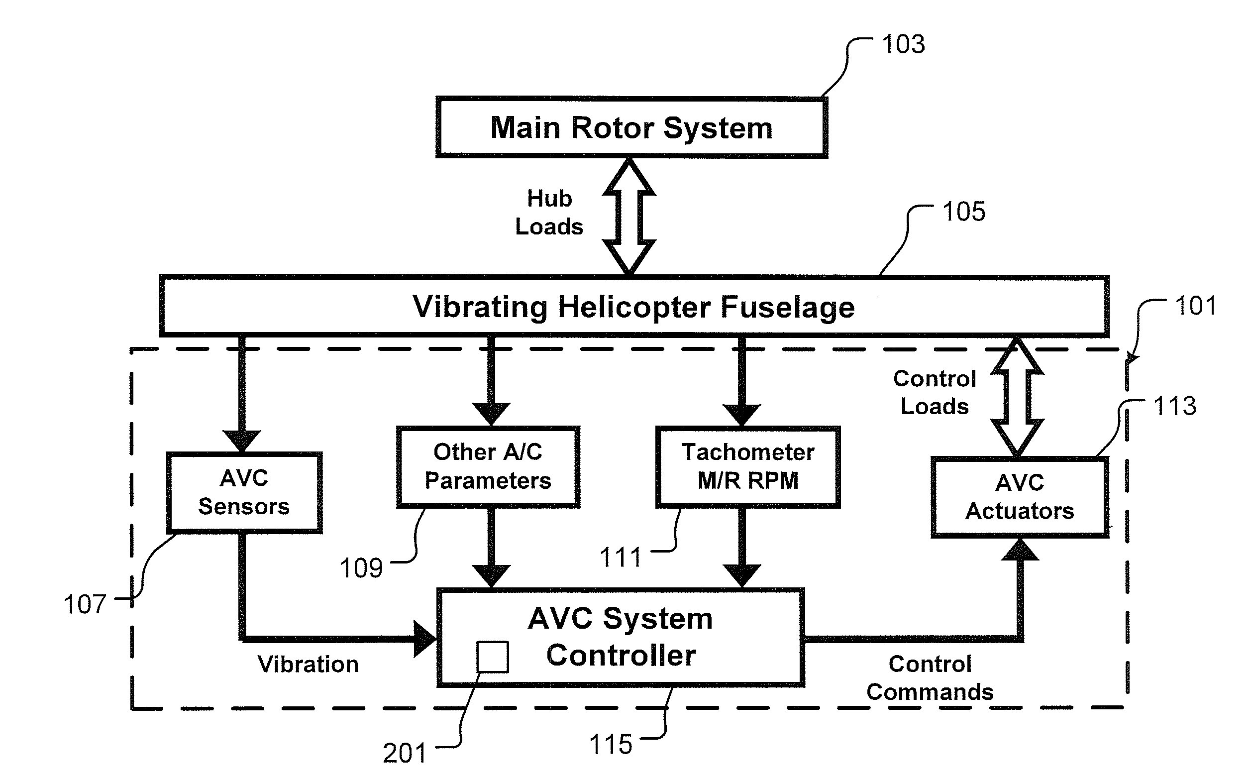
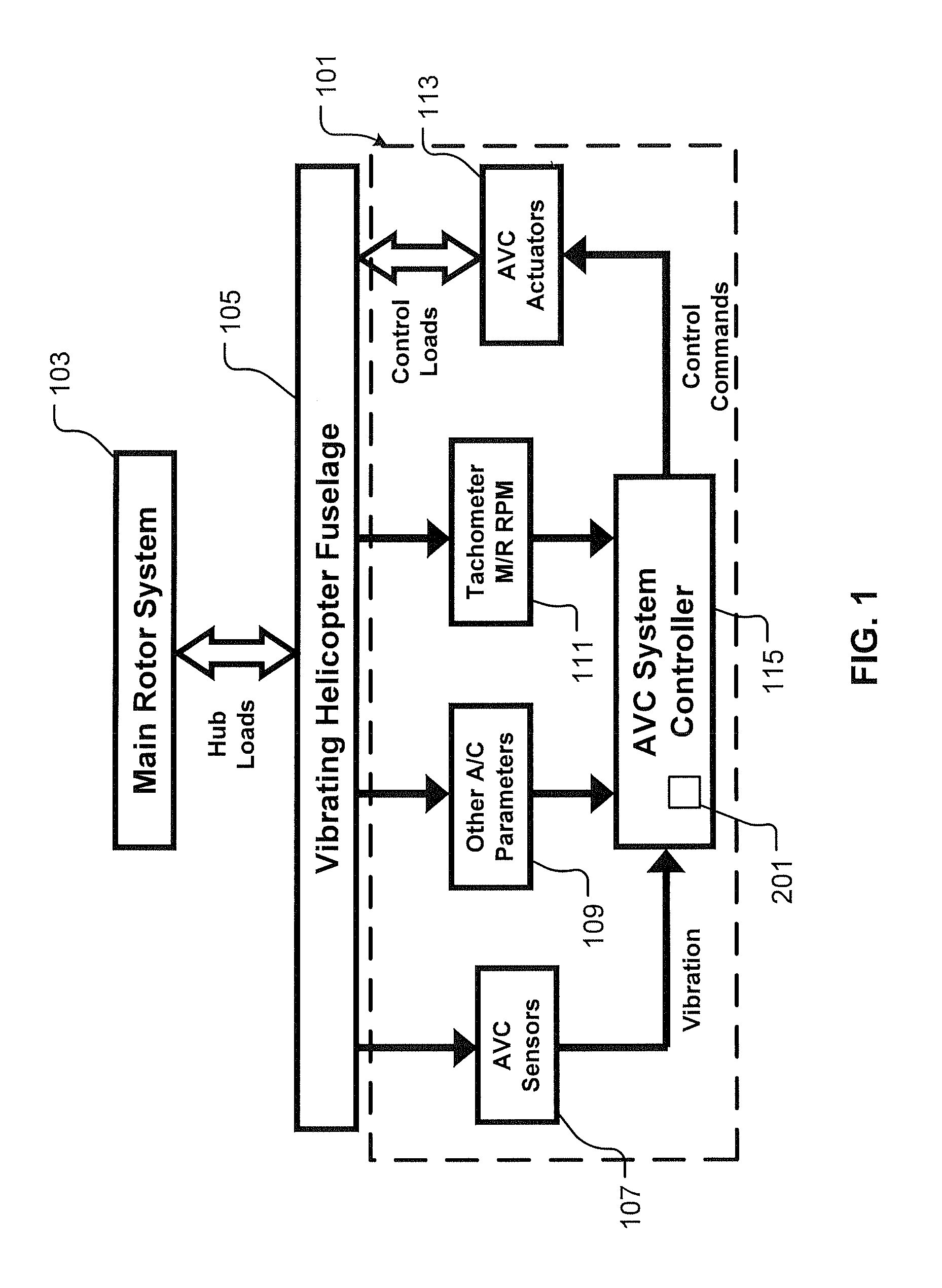
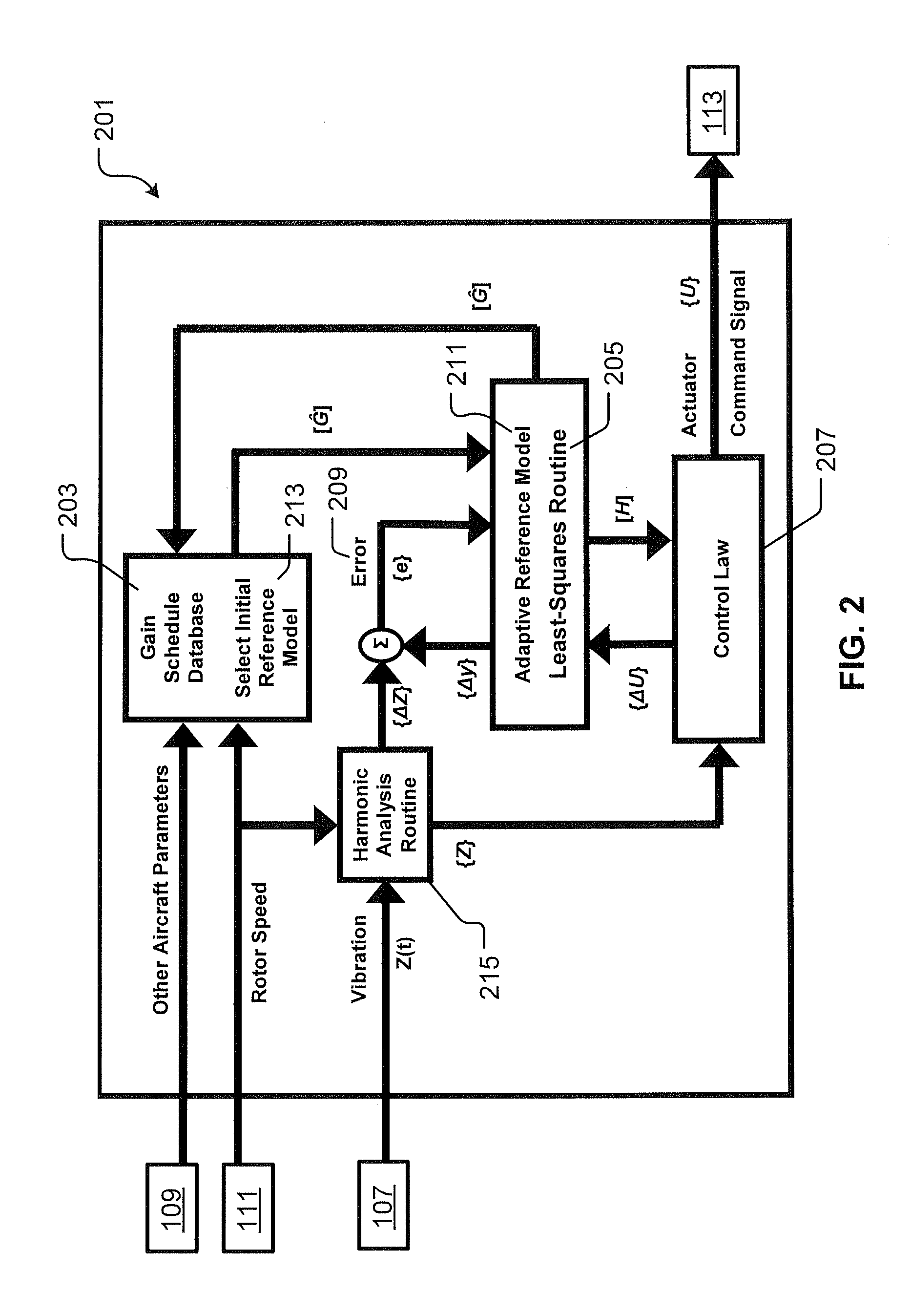
The adaptive reference model algorithm uses a gain scheduling feature combined with a customized Least-Squares routine as an adaptive method for adjusting feedback control so as to account for variations in Transfer Function (G), thereby optimizing the effectiveness of the Active Vibration Control (AVC) System. The Least-Squares routine identifies the transfer function in a background process without interruption of closed loop vibration control. This identification approach is accomplished without intentional interrogation of the AVC actuators and without intentional vibration level changes. For this adaptive control logic, the dynamic relationship between AVC actuators and AVC sensors is represented by a mathematical model of Transfer Function (G). The mathematical model of Transfer Function (G) is continuously updated by the Least-Squares routine. A feedback gain (H) is computed from the mathematical model of Transfer Function (G), and the feedback gain (H) is updated each time the mathematical model of Transfer Function (G) is updated.

Description

TECHNICAL FIELD[0001]The present application relates to vibration control in rotorcraft.DESCRIPTION OF THE PRIOR ART[0002]Aircraft, such as rotorcraft, experience vibration concerns due in part to one or more large rotating rotors. Rotors are a primary source of vibration upon the fuselage of rotorcraft. Significant fuselage vibrations can contribute to flight control problems, material fatigue, maintenance costs, and pilot fatigue, to name a few. Significant time and expense has been spent in the rotorcraft industry in attempts to reduce and cancel rotorcraft vibrations. Traditionally, rotorcraft vibrations have been addressed with passive devices, such as vibration isolation systems and dynamic absorbers. These passive devices, which are tuned relative to the operating frequency of the aircraft rotor, have proven to be very effective for legacy rotorcraft. However, variable rotor speed (RPM) rotorcraft configurations are becoming more attractive in part due to initiatives to impro...

Claims


Application Information

Patent Timeline
IPC IPC(8): B64C27/54
CPCG10K2210/1281B64C2027/004G10K11/1788B64C27/001G10K2210/3012G10K2210/3056F16F15/002G10K2210/3055G10K11/17883G10K11/17879G10K11/17854G10K11/17823G10K11/17817G10K11/17857
Inventor HEVERLY, II, DAVID E.SINGH, RUPINDERPAPPAS, JOHN
Owner TEXTRON INNOVATIONS
Learn More