Color wheel, manufacturing method of the color wheel, and projector including the color wheel

a technology of color wheel and manufacturing method, which is applied in the direction of color measuring device, instrument, projector, etc., can solve the problems of difficult adjustment of chromaticity, inadequacies of high-pressure mercury vapor lamp or xenon lamp, and irregular color appearance, so as to prevent irregular color occurrence, improve the chromaticity of images projected, and ensure the durability of the color wheel for the projector

Inactive Publication Date: 2011-12-15
MINEBEA CO LTD
View PDF0 Cites 28 Cited by
  • Summary
  • Abstract
  • Description
  • Claims
  • Application Information

AI Technical Summary

Benefits of technology

[0037]The projector of the above comprises the color wheel for a projector in its projection optical system, the color wheel being formed as that the phosphor layer, the thickness of which is constant in a radius direction of the color wheel, is formed in a predetermined area of the color wheel in its circumferential direction. Accordingly, it would be possible to prevent the occurrence of irregular color in the color wheel for a projector so as to improve the chromaticity of images projected on a projector.
[0038]Since the present invention is structured as discussed hereinabove, it makes possible to provide a color wheel where durability of the color wheel for a projector is not deteriorated while occurrence of irregular color can be prevented. Further, the present invention can surely contribute to improvement of chromaticity of a projector where a color wheel is included in its projection optical system such as the hybrid type projector, etc.

Problems solved by technology

Due to content of mercury or problems caused by calorific values, the high-pressure mercury vapor lamp or the xenon lamp appears to be not appropriate.
When making the thickness of the phosphor additive resin become uneven, the thickness of phosphors becomes non-uniform, becoming one cause of making the adjustment of its chromaticity difficult.
With this, it can reduce the spread of resin after being coated on the substrate; however, in general, since the resin having high heat resistance and superior light permeability has low viscosity, it will cause a problem that the durability of a color wheel is deteriorated.

Method used


Image

  • Color wheel, manufacturing method of the color wheel, and projector including the color wheel
  • Color wheel, manufacturing method of the color wheel, and projector including the color wheel
  • Color wheel, manufacturing method of the color wheel, and projector including the color wheel

Examples


first embodiment

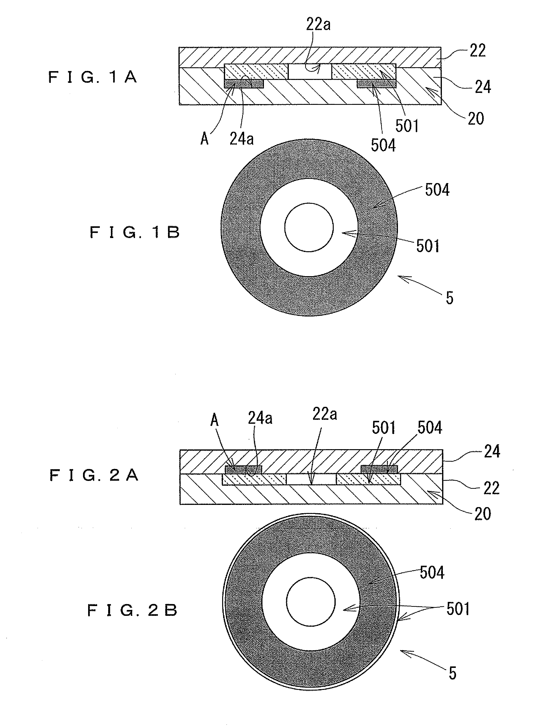
[0051]First, the manufacturing method of a color wheel for a projector according to the present invention will be explained. Schematically, as shown in FIG. 1A, a phosphor layer contour correcting device 20 is employed, the phosphor layer contour connecting device 20 having a concavity by which a space A is formable on the surface of the color wheel substrate 501. A desired phosphor layer contour, the thickness of which is constant in the radius direction of the color wheel substrate 501, can be thus obtained. Phosphor additive resin 504 is then injected into and sealed in the space A formed between the surface of the color wheel substrate 501 and the concavity of the phosphor layer contour correcting device 20. In this condition, the phosphor additive resin 504 is heated. Here, the phosphor additive resin 504 may be first temporarily heated by, for example, a heater built-in the phosphor layer contour correcting device 20. Then, as necessary, after the phosphor layer contour correc...

third embodiment

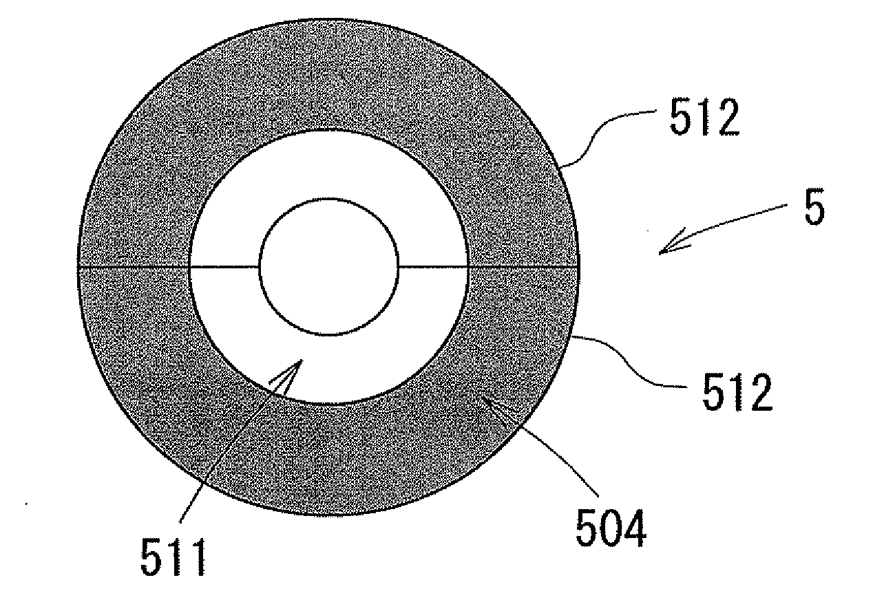
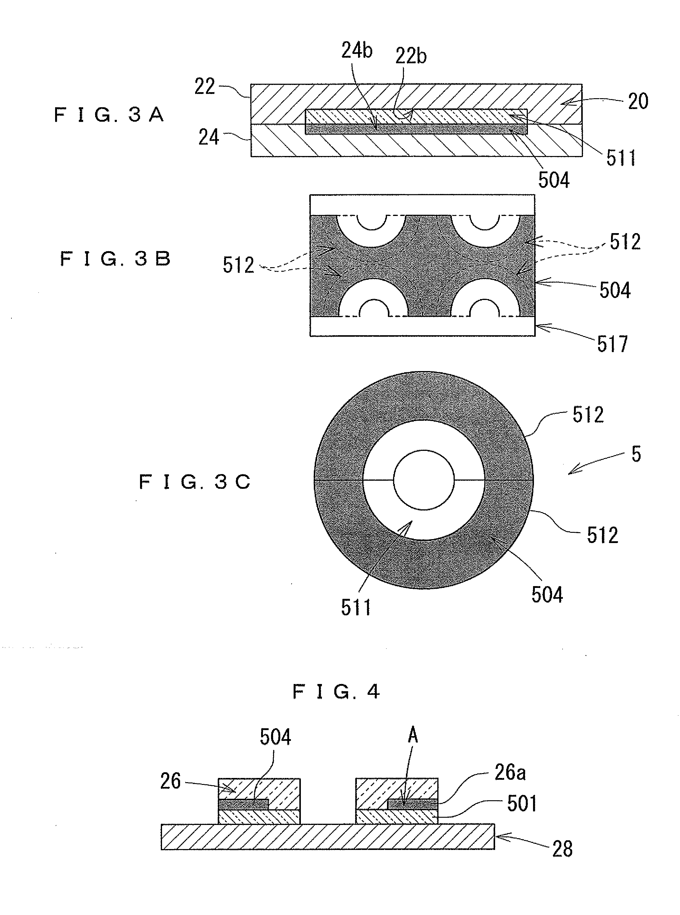
[0062]In the present invention, the non-circular substrate 511 is employed for the color wheel substrate. As exemplified in FIG. 3, the non-circular substrate 511 is formed into a rectangle. At least one piece of segment 512 composing the color wheel 5 can be cut out from the non-circular substrate 511. The segment 512 shown in FIG. 3 is formed into a semi-circle) (180°) whereby the complete color wheel 5 is formable by two pieces of the segments 512. However, as necessary, the segment 512 may be further divided. As the first die 22, a die having a cavity 22b in which the non-circular substrate 511 is positioned is used. Further, as the second die 24, a die having a cavity 24b is used. Here, the cavity 24b of the die forms a space patterning a desired phosphor layer configuration for at least one segment 512 on the surface of the non-circular substrate 511 positioned in the cavity 22b of the first die 22. The first die 22 and the second die 24 are clamped. After the phosphor additiv...

fifth embodiment

[0069]In the present invention, as shown in FIG. 5A, the cavity of the second die 24 has a surface on which a convexoconcave configuration 24c is formed. This convexoconcave configuration 24c has a shape that forms an antireflection structure 30 each shown from FIG. 5D to FIG. 5F. The convexoconcave configuration 24c transfers a predetermined convexoconcave forms on the surface of the phosphor additive rein 504 so as to constitute the surface of the phosphor additive resin 504 by itself to have an antireflection structure. Here, FIG. 5D to FIG. 5F exemplify the configuration of the antireflection structure 30. The antireflection structure 30A where the wall of its square pyramid is structured by a curved surface while the upper end portion of the square pyramid is made flat has the lowest reflective ratio and has a wide conical aperture. The antireflective ratio will be lowered in order of an antireflection structure 30B with a simple square pyramid and an antireflection structure 3...


PUM


Abstract

There is provided a manufacturing method of a color wheel for a projector. The method includes contacting a phosphor layer contour correcting device on a surface of a color wheel substrate, the phosphor layer contour correcting device having a concavity to form a space that patterns a desired phosphor layer contour, the length of which is constant in a radial direction; injecting phosphor additive resin into the space that is composed of a surface of the color wheel substrate and the concavity of the phosphor layer contour correcting device; maintaining the phosphor additive resin in the space; and heating the phosphor additive resin.

Description

BACKGROUND OF THE INVENTION[0001]1. Field of the Invention[0002]The present invention relates to a color wheel for a projector that projects and enlarges a display image by means of a projection optical system so as to obtain a large display image, and the manufacturing method of the color wheel. The present invention also relates to a projector that includes the color wheel in its projection optical system.[0003]2. Description of the Related Art[0004]A projector (a projection-type image display device) used in home theaters, presentations, etc. in which to magnify and project displayed images by means of a projection optical system so as to obtain large-screen displayed images has been commercialized. This type of projector displays, while applying light that is projected from a light source as an illuminant, images on a screen through an electro-optical device using a spatial optical modulator such as a digital micromirror device or a liquid crystal display device. The projector m...

Claims


Application Information

Patent Timeline
Patent Type & Authority Applications(United States)
IPC IPC(8): G03B21/14G01J3/52
CPCG03B21/204
Inventor KATO, HIDEKIKITAMURA, ATSUSHI
Owner MINEBEA CO LTD
Why Eureka
Try Eureka