Supercharge Your Innovation With Domain-Expert AI Agents!

Rotor Blade Assembly

Active Publication Date: 2011-12-15
SIEMENS GAMESA RENEWABLE ENERGY AS
View PDF4 Cites 8 Cited by
  • Summary
  • Abstract
  • Description
  • Claims
  • Application Information

AI Technical Summary

Benefits of technology

[0006]Hence, it is an object of the invention to provide a rotor blade assembly with a simple and secure connection of a rotor blade tip member and a rotor blade.
[0021]The rotor blade tip member may have the shape of a winglet. Thus, in dependence of the shape of the winglet, the aerodynamic properties of the blade tip member may be improved or adjusted.

Problems solved by technology

Thereby, a known problem occurs from the connecting means connecting the extending member to the basic structure of the rotor blade since their ability to keep the extending member in firm and secure contact to the basic structure of the rotor blade decreases with time.
This may lead to a loss of the extending member in the worst case, which is a significant safety problem in particular during operation of the wind turbine.

Method used


Image

  • Rotor Blade Assembly
  • Rotor Blade Assembly
  • Rotor Blade Assembly

Examples


first embodiment

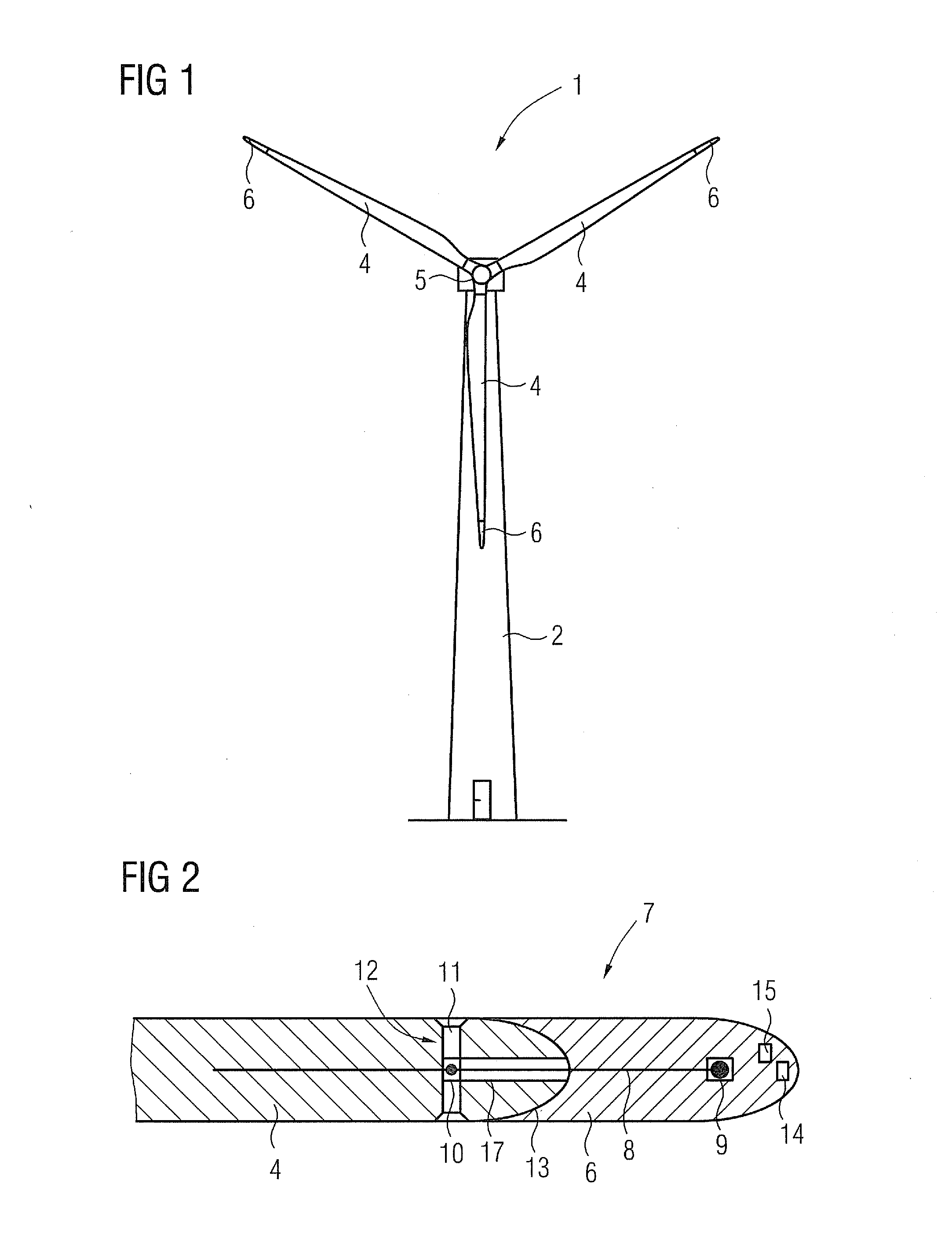
[0029]FIG. 2 shows a principle cut view of a rotor blade assembly 7 according to the invention, essentially comprising the rotor blade 4 and the cap-like shaped blade tip member 6. A mechanical and electrical connection of the blade tip member 6 with the rotor blade 4 is merely established by means of the metal rod 8 being locked to an anchor 9 at the side of the blade tip member 6 and to an anchor 10 disposed at a lightning receptor 11, which is a part of a lightning conductor 12 at the side of the rotor blade 4. Hence, the rod 8 represents the only connecting means providing a firm connection of the blade tip member 6 and the rotor blade 4.

[0030]Hence, the inventive connecting principle does not rely on adhesives applied on the rotor blade structure which may degrade in strength due to aging, environmental influences and / or local heating of the blade tip member as a consequence of a lightning stroke hitting the wind turbine.

[0031]Generally, the connection of the blade tip member 6...

second embodiment

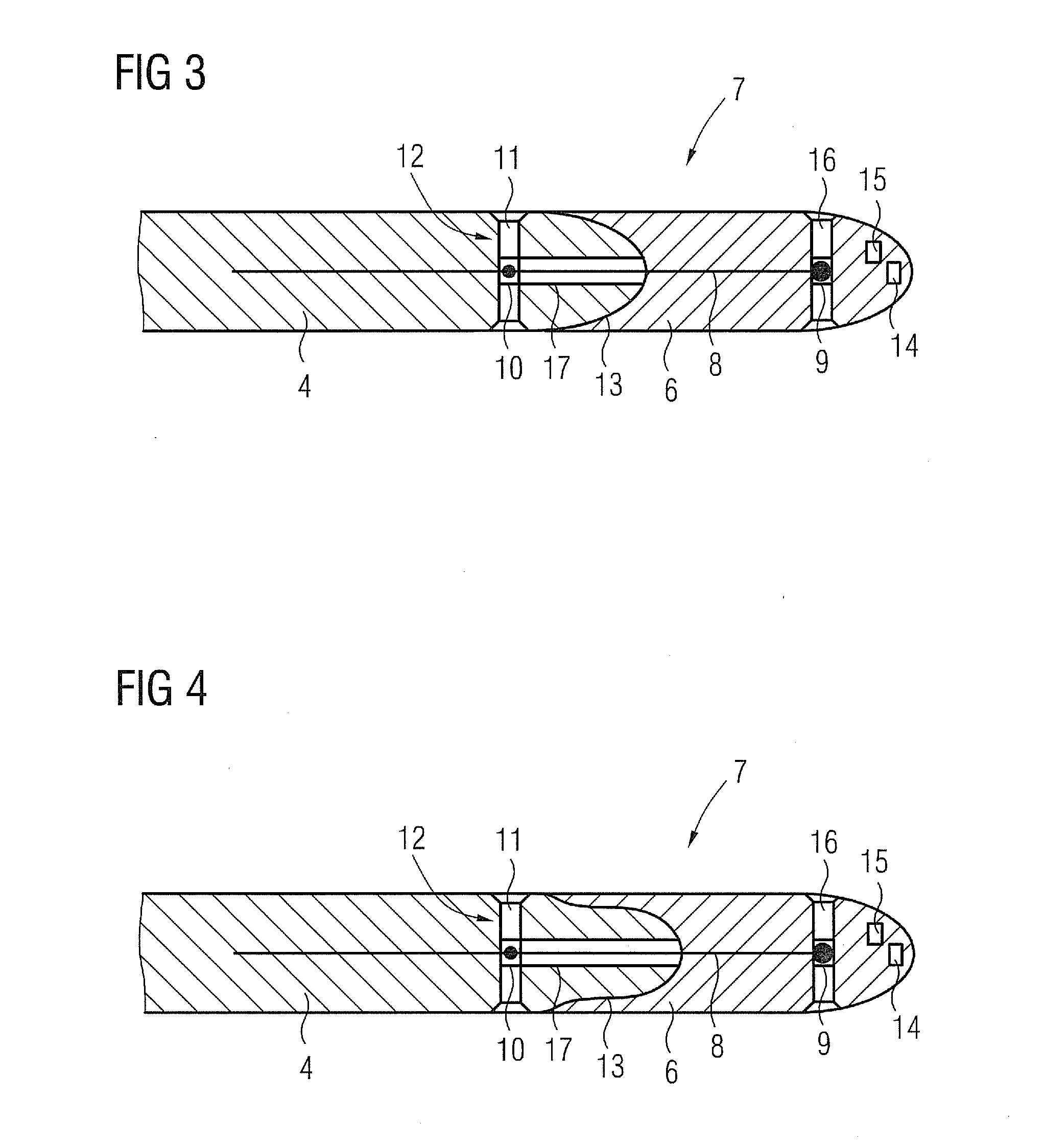
[0035]FIG. 3 shows a principle cut view of a rotor blade assembly 7 according to the invention, whereby same parts are denoted with same reference numbers. The essential difference to the embodiment according to FIG. 1 is that the anchor 9 holding the rod is integrated into a further lightning receptor 16 disposed within the blade tip member 6. Hence, the lightning conductor 12 of the rotor blade 4 is elongated by means of the electrically conductive rod 8 and the further lightning receptor 16 integrally comprising the anchor 9, so as to build an electrical connection from the lightning receptor 16 along the anchor 9, the rod 8, to the lightning conductor 12 disposed within the rotor blade 4.

third embodiment

[0036]As discernible from FIG. 4 showing a principle cut view of a rotor blade assembly 7 according to the invention the free ending of the rotor blade 6 has is of reduced cross-section, whereby the connecting portion 13 of the cap-like shaped blade tip member 6 overlaps the portion of reduced cross-section, that is the portion of reduced cross-section engages with the connecting portion 13 of the blade tip member 6 in teens of a plug-connection. Again, a desired outer profile of the rotor blade 4 is formed by means of the form closure between the blade tip member 6 and the rotor blade 4.


PUM


Abstract

A rotor blade assembly is provided that includes a rotor blade and a rotor blade tip member. The rotor blade is provided with an integrated lightning down conductor and is attachable or attached to a rotor hub of a wind turbine. The rotor blade tip member is made of an electrically insulating material and is detachably attached or adapted to be detachably attached to a free ending of the rotor blade by a connecting device. The connecting device is a wire or a rod made of an electrically conductive material establishing or adapted to establish a mechanical and electrical connection of the rotor blade tip member with the lightning down conductor of the rotor blade.

Description

CROSS REFERENCE TO RELATED APPLICATIONS[0001]This application claims priority of European Patent Office application No. 10165721.1 EP filed Jun. 11, 2010, which is incorporated by reference herein in its entirety.FIELD OF INVENTION[0002]The invention relates to a rotor blade assembly comprising a rotor blade with an integrated lightning down conductor, the rotor blade being attachable or attached to a rotor hub of a wind turbine, whereby a rotor blade tip member made of an electrically insulating material is adapted to be detachably attached or detachably attached to the free ending of the rotor blade by means of a connecting means.BACKGROUND OF INVENTION[0003]Nowadays, various types of wind turbines comprise a separate rotor blade tip member disposed at the free endings of the respective rotor blades. Therefore, diverse connecting means providing a firm connection of the rotor blade tip member to the basic structure of the rotor blade are known. Thereby, usually adhesive means, bol...

Claims


Application Information

Patent Timeline
IPC IPC(8): F03D11/00
CPCF03D1/065F03D11/0033F05B2240/221F05B2240/30F05B2250/70F05B2250/711Y02E10/722F05B2260/30F05B2280/1071F05B2280/2001F05C2201/0448F05C2203/02Y02E10/721F05B2250/712F03D80/30Y02E10/72
Inventor STIESDAL, HENRIK
Owner SIEMENS GAMESA RENEWABLE ENERGY AS
Features
  • R&D
  • Intellectual Property
  • Life Sciences
  • Materials
  • Tech Scout
  • Unparalleled Data Quality
  • Higher Quality Content
  • 60% Fewer Hallucinations
Learn More