
Ceiling fan vane structure

a technology for ceiling fans and vanes, which is applied in the direction of marine propulsion, liquid fuel engines, and vessel construction, etc., can solve the problems of poor ventilation, high cost of wood, and limited effect of facilitating airflow through windows and doors, so as to reduce reduce the total weight of vanes , the effect of reducing the load of motors

Inactive Publication Date: 2011-12-15
ZHONGSHAN HSIANGYUAN WOOD
View PDF5 Cites 5 Cited by
  • Summary
  • Abstract
  • Description
  • Claims
  • Application Information

AI Technical Summary

Benefits of technology

[0008]In view of the drawbacks of the conventional ceiling fan vane structure, the inventor of the present invention based on years of experience in the related industry to conduct extensive researches and experiments, and finally developed an improved ceiling fan vane structure in accordance with the present invention to achieve the effect of minimize the total weight of vanes of the ceiling fan to reduce the load of a motor of the ceiling fan without affecting the structural strength of the vanes, so as to reduce loads, improve the overall operation efficiency, and achieve the power saving effect.
[0009]It is a primary objective of the present invention to overcome the shortcomings of the prior art by providing a structural design that stuffs a lighter material inside the vanes to reduce the weight of the vanes, while maintaining the required structural strength.
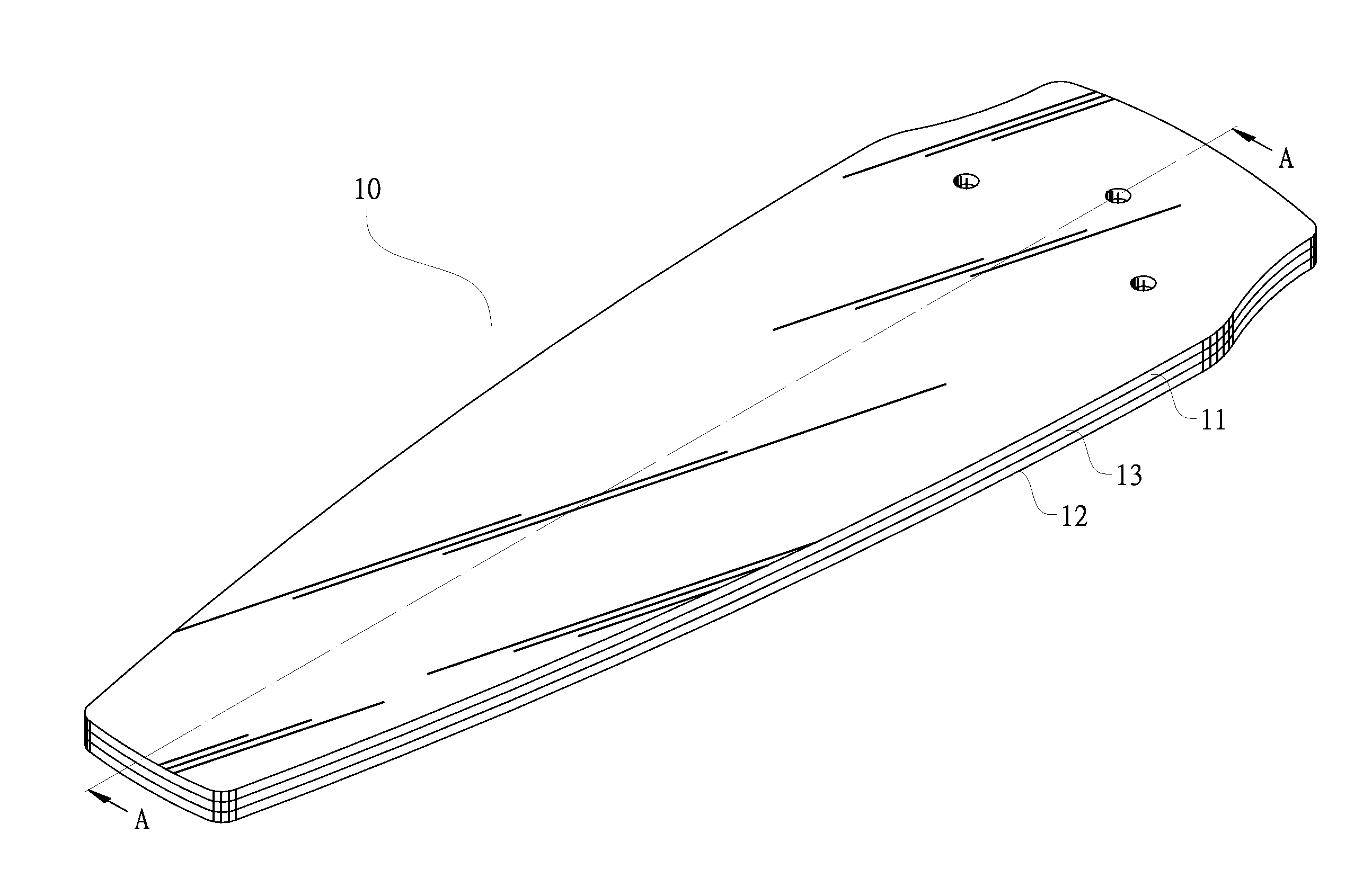
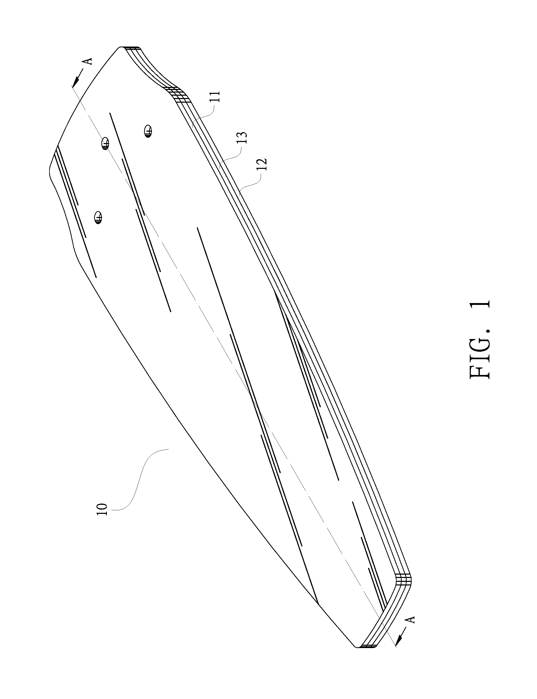
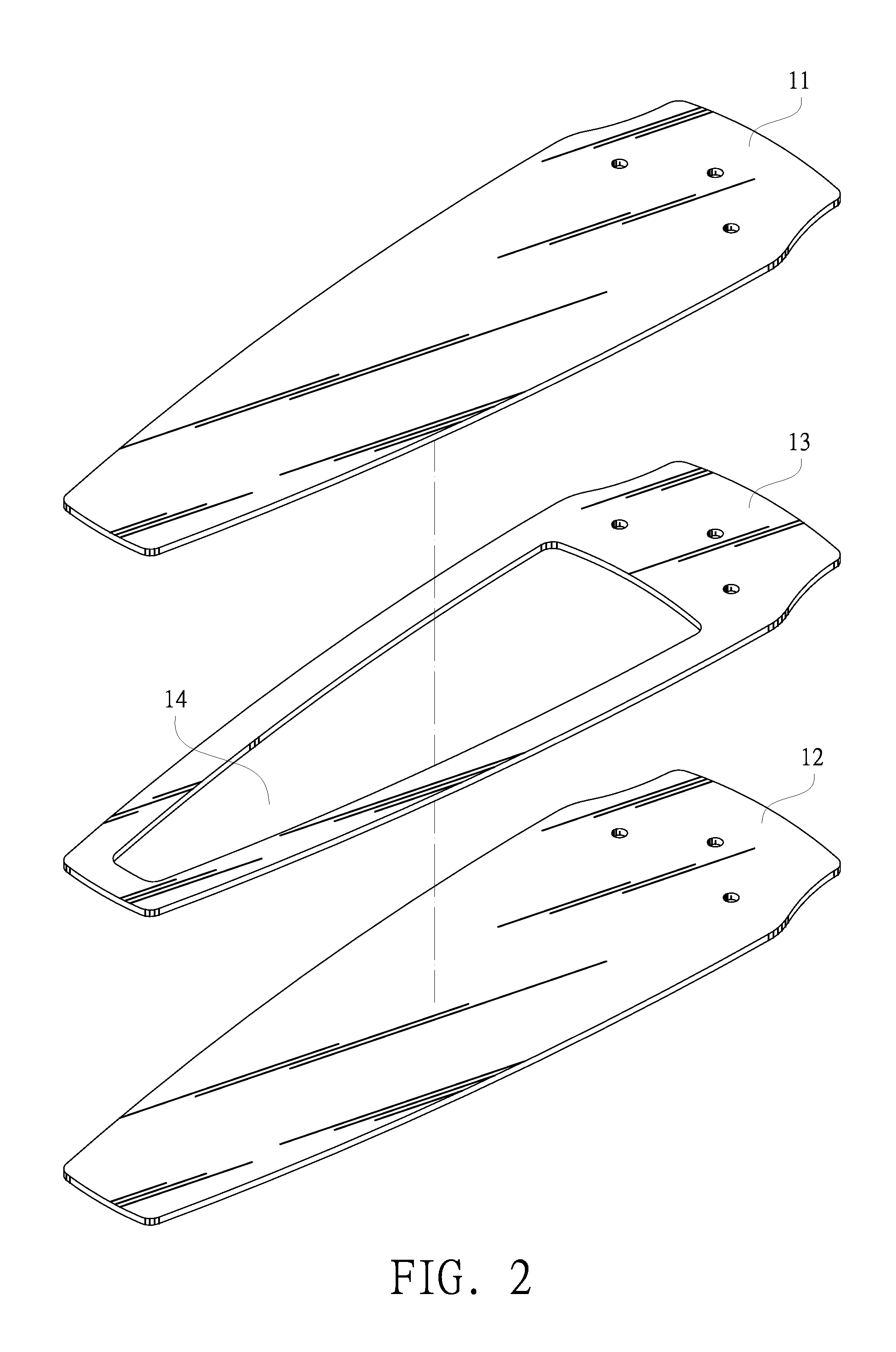
[0010]To achieve the foregoing objective, the present invention provides a structural design comprises vanes of a ceiling fan, and each vane is composed of a plurality of laminated plates, of which a middle laminated plate has a hollow slot formed thereon, such that after the vanes are combined and formed, a hollow chamber is formed in the vane, and the hollow chamber can be maintained hollow, or filled with a lightweight material such as glass fiber, cotton, or foam to achieve the effect of reducing the weight of the vanes, so that when a motor of the fan is operated to drive the vanes to rotate and produce air turbulence, the lightweight vanes can reduce the load of the motor to improve its operation efficiency, and achieve the effects of saving power and extending the lifespan of the motor.

Problems solved by technology

However, the effect of facilitating airflows made by the windows and doors is very limited, and in certain situations such as the usage of air-conditioning, a rainy day or a poor outdoor air quality, it is necessary to close the windows and doors.
As a result, the ventilation is poor, and the poor ventilation causes a hot and humid indoor environment, and a ceiling fan is generally used for producing air currents and turbulence to lower the indoor temperature and improve the hot and humid environment.
The vanes of such ceiling fan are generally made of wooden plates, but wood is expensive and the manufacturing cost will be increased significantly.
However, the vanes of this sort made of wooden plates have a relatively heavy weight, causing a relatively large load to the motor of the ceiling fan, and affecting the operation efficiency of the motor.
As a result, the ceiling fan consumes more electric power and results in more expenses.

Method used


Image

  • Ceiling fan vane structure
  • Ceiling fan vane structure
  • Ceiling fan vane structure

Examples


Embodiment Construction

[0016]The structural assembly, technical characteristic and effects of the present invention will become apparent with the detailed description of preferred embodiments and the illustration of related drawings.

[0017]With reference to FIG. 1 for a schematic view of a structure, FIGS. 2 and 3 for exploded views of a structure, and FIGS. 4 and 5 for schematic views of a structural relation in accordance with the present invention respectively, an improved structure of vanes comprises a plurality of vanes 10 formed by combining a plurality of laminated plates including an upper laminated plate 11, a lower laminated plate 12, and one or more middle laminated plates 13, and the laminated plates 11, 12, 13 have shapes and profiles corresponding with one another, and the thickness of each of the plates 11, 12, 13 can be designed to be the same or different, and the middle laminated plate 13 includes one or more hollow slots 14 formed at predetermined positions respectively. If there are mor...


PUM


Abstract

An improved ceiling fan vane structure minimizes the weight of vanes to reduce to loads and achieve a power saving effect without affecting the structural strength of the vanes. The structural design includes the vanes, each being formed by combining a plurality of laminated plates, in which a middle laminated plate has a hollow slot, and a hollow chamber is created after the vanes are formed. The hollow chamber is maintained hollow or filled with a lightweight material such as glass fiber, cotton, or foam to achieve the effect of reducing the weight of the vanes, so that when a motor of the fan is operated to drive the vanes to rotate and produce air turbulence, the lightweight vanes can reduce the load of the motor to improve its operation efficiency, and achieve the effects of saving power and extending the lifespan of the motor.

Description

BACKGROUND OF THE INVENTION[0001]1. Field of the Invention[0002]The present invention relates to an improved ceiling fan vane structure, and more particularly to a structure that minimizes the weight of vanes to reduce the load of a motor of a ceiling fan without affecting the structural strength of the vanes, so as to achieve the effects of improving the operation efficiency to save power, and extending the lifespan of the motor of the ceiling fan.[0003]2. Description of the Related Art[0004]In general, windows and doors are available in our living space for facilitating indoor and outdoor airflows, and preventing stale air in the house. However, the effect of facilitating airflows made by the windows and doors is very limited, and in certain situations such as the usage of air-conditioning, a rainy day or a poor outdoor air quality, it is necessary to close the windows and doors. As a result, the ventilation is poor, and the poor ventilation causes a hot and humid indoor environme...

Claims


Application Information

Patent Timeline
Patent Type & Authority Applications(United States)
IPC IPC(8): F04D29/38
CPCF04D29/388F04D25/088
Inventor SHIH-CHUNG, YU
Owner ZHONGSHAN HSIANGYUAN WOOD
Learn More