Simultaneous Integral Milling Operation Machine

Inactive Publication Date: 2011-12-22
PACIFIC BEARING
View PDF8 Cites 7 Cited by
  • Summary
  • Abstract
  • Description
  • Claims
  • Application Information

AI Technical Summary

Benefits of technology

[0010]The embodiments described herein provide new and improve machining apparatuses and methods of machining independent surfaces into a work piece. These embodiments provide new and improved machining apparatuses and methods of machining independent surfaces into a work piece while a work piece makes a single pass along a feed path. These new and improved embodiments also reduce machining time for the work piece. Additionally, the embodiments described herein increase the dimensional accuracy between the plurality of different independent surfaces of the

Problems solved by technology

Unfortunately, certain types of rails are extruded elongated parts and are prone to the mechanical deflections often associated with extruded elongated parts.
In many cases, a single datum surface is not enough, and therefore a work piece must be repositioned several times to complete the manufacture of the work piece.
Several problems arise by stopping to refixture a work piece.
First, many geometrical dimensions, e.g. flatness, parallelism, and perpendicularity, require a high degree of dimensionally accuracy, often referred to as “tight tolerances.” By stopping to refixture, i.e. “breaking set up,” the original datum surface that previously machined dimensions indicate from is lost.
As a result, any future machined surfaces indicating from the original datum surface after breaking set up and refixturing will possess an inherent margin of error

Method used


Image

  • Simultaneous Integral Milling Operation Machine
  • Simultaneous Integral Milling Operation Machine
  • Simultaneous Integral Milling Operation Machine

Examples


Embodiment Construction

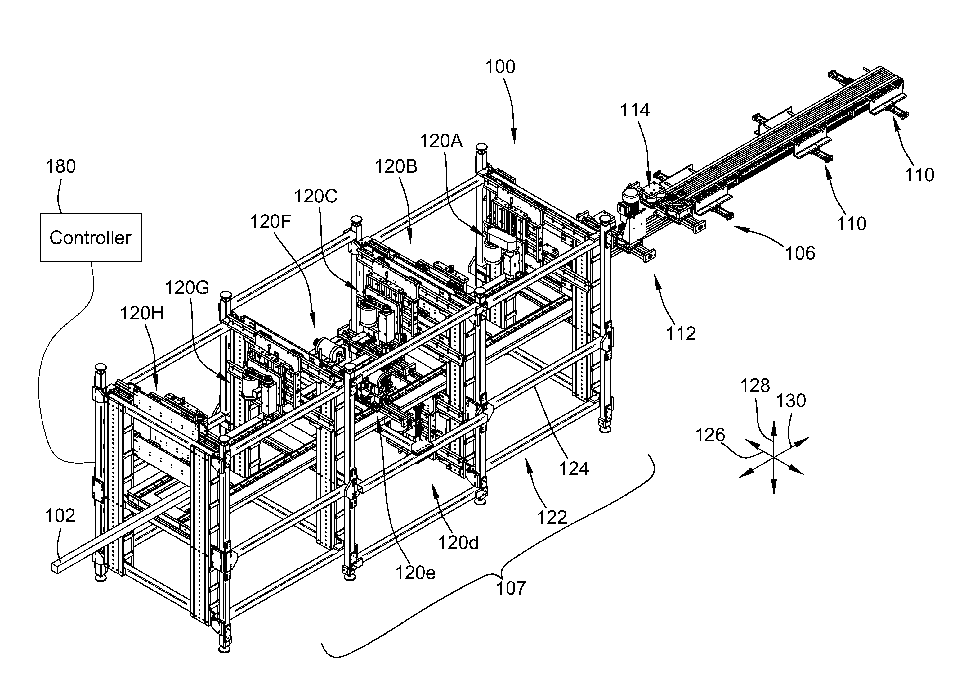
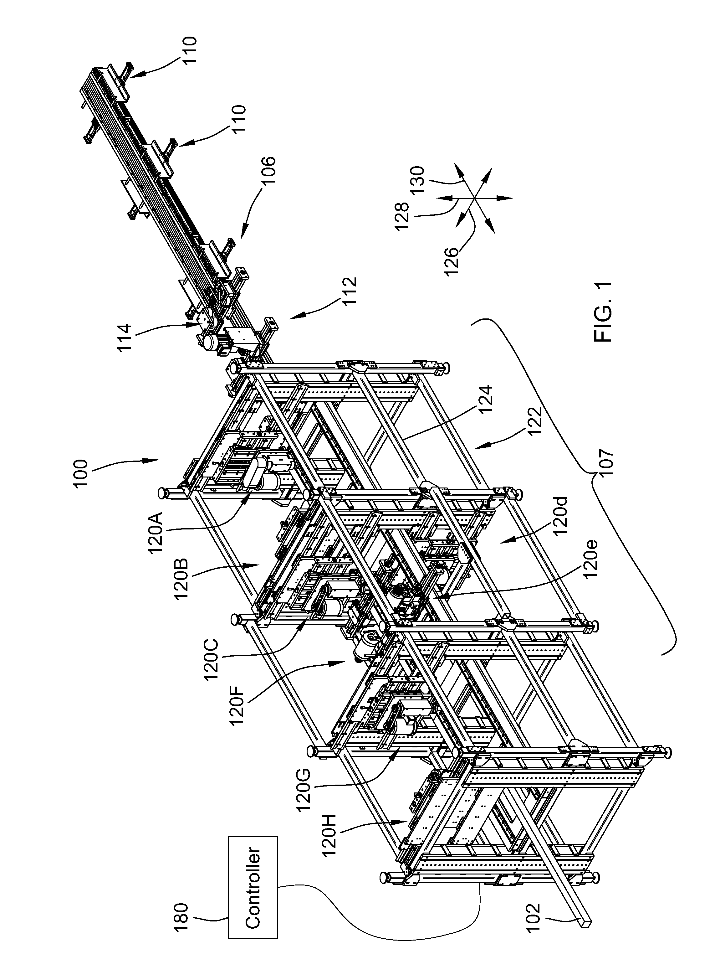
[0037]FIG. 1 illustrates a simplified representation of an embodiment of a machining apparatus 100 according to the teachings of the present invention. The machining apparatus 100 is used to machine multiple independent surfaces of a work piece 102 as the work piece 102 passes in a feed direction illustrated as arrow 130 along a feed path 104 and through the machining apparatus 100. The machining apparatus achieves this functionality through the use of multiple machining stations 120A-H.

[0038]As will be more fully explained below, the machining stations 120A-H are arranged along a linear feed path 104. The work piece 102 is fed along the feed path 104 by a feed arrangement 106. Various ones of the machining stations 120A-H simultaneously machine various ones of independent surfaces 150A-F of the work piece 102 (see FIG. 8). It will be recognized that the ordering of the machining stations 120A-H is not limited to the illustrated embodiment of FIG. 1. Indeed, other orderings of the m...


PUM

PropertyMeasurementUnit
Dimensionless propertyaaaaaaaaaa
Lengthaaaaaaaaaa

Abstract

A machining apparatus and method of machining a work piece are provided. The method generally includes machining a plurality of independent surfaces of the work piece as the work piece travels along a work path and through a plurality of machining stations in a single pass. The machining apparatus includes a frame and first and second machining stations mounted to the frame. Each machining station is configured to form an independent surface in a work piece passed through the machining apparatus. The machining apparatus also includes a feed arrangement for feeding the work piece through the apparatus along a feed path and relative to the first and second machining stations and the frame while machining is performed on the work piece.

Description

CROSS-REFERENCE TO RELATED PATENT APPLICATIONS[0001]This patent application is a continuation of co-pending PCT Patent Application No. PCT / US2009 / 069905, filed Dec. 31, 2009, and claims the benefit of U.S. Provisional Patent Application No. 61 / 141,950, filed Dec. 31, 2008, the entire teachings and disclosures of which are incorporated herein by reference thereto.FIELD OF THE INVENTION[0002]This invention generally relates to machining apparatuses and methods of machining a work piece.BACKGROUND OF THE INVENTION[0003]Manufacturing of parts and devices includes numerous types of processes for forming parts or objects into desired shapes. One particular manufacturing process includes machining a work piece to a desired shape. Machining may include, but is not limited to, grinding, cutting, lapping, sanding, milling and polishing the work piece to have the desired shape or profile. To increase output, machining of work pieces has become automated. However, to have accurately machined sh...

Claims


Application Information

Patent Timeline
IPC IPC(8): B23P23/06B23P13/00
CPCB23C1/10B23C3/002B23Q11/0046Y10T29/5122F16C29/005Y10T29/49996B23Q39/028F16C2322/39
Inventor SCHROEDER, ROBERTO'CONNOR, WILLIAM E.OLDENBURG, DENNIS L.
Owner PACIFIC BEARING
Why Eureka
Try Eureka