Refrigerating cycle apparatus

a technology of refrigerating cycle and apparatus, which is applied in the direction of domestic cooling apparatus, lighting and heating apparatus, and cooling fluid circulation, etc., can solve the problems of reducing air conditioning capacity, unexpected refrigerant leakage, and affecting the operation of the apparatus, etc., to achieve accurate determination of excess/shortage, easy maintenance, and high reliability

Active Publication Date: 2011-12-22
MITSUBISHI ELECTRIC CORP
View PDF1 Cites 59 Cited by
  • Summary
  • Abstract
  • Description
  • Claims
  • Application Information

AI Technical Summary

Benefits of technology

[0031]The refrigerating cycle apparatus according to the present invention is advantageous in that it can accurately determine the excess / shortage of the refrigerant amount in the refrigerating cycle apparatus under any environmental condition and any installation condition, by calculating the refrigerant amount in the refrigeration circuit based on the operation state amount of the refrigerating cycle, and comparing the calculative refrigerant amount with an appropriate refrigerant amount stored in a storage part. As a result, a refrigerant cycle apparatus that is highly reliable and easy to maintain can be obtained.

Problems solved by technology

In this refrigerating cycle apparatus, if a connecting portion such as a pipe is not fastened sufficiently, the refrigerant may leak gradually through a gap in the fastening portion of the pipe or the like over a long-term use of the refrigerating cycle apparatus.
Damage to the pipe may lead to an unexpected refrigerant leakage.
The refrigerant leakage causes a decrease in air conditioning capacity and damage to the constituent devices.
In a serious case, the refrigerating cycle apparatus may have to be stopped for safety reasons.
If the refrigerating circuit is charged with the refrigerant excessively, the liquid refrigerant runs under a pressure in the compressor for long period of time, leading to a failure.

Method used


Image

  • Refrigerating cycle apparatus
  • Refrigerating cycle apparatus
  • Refrigerating cycle apparatus

Examples


embodiment 1

Apparatus Configuration

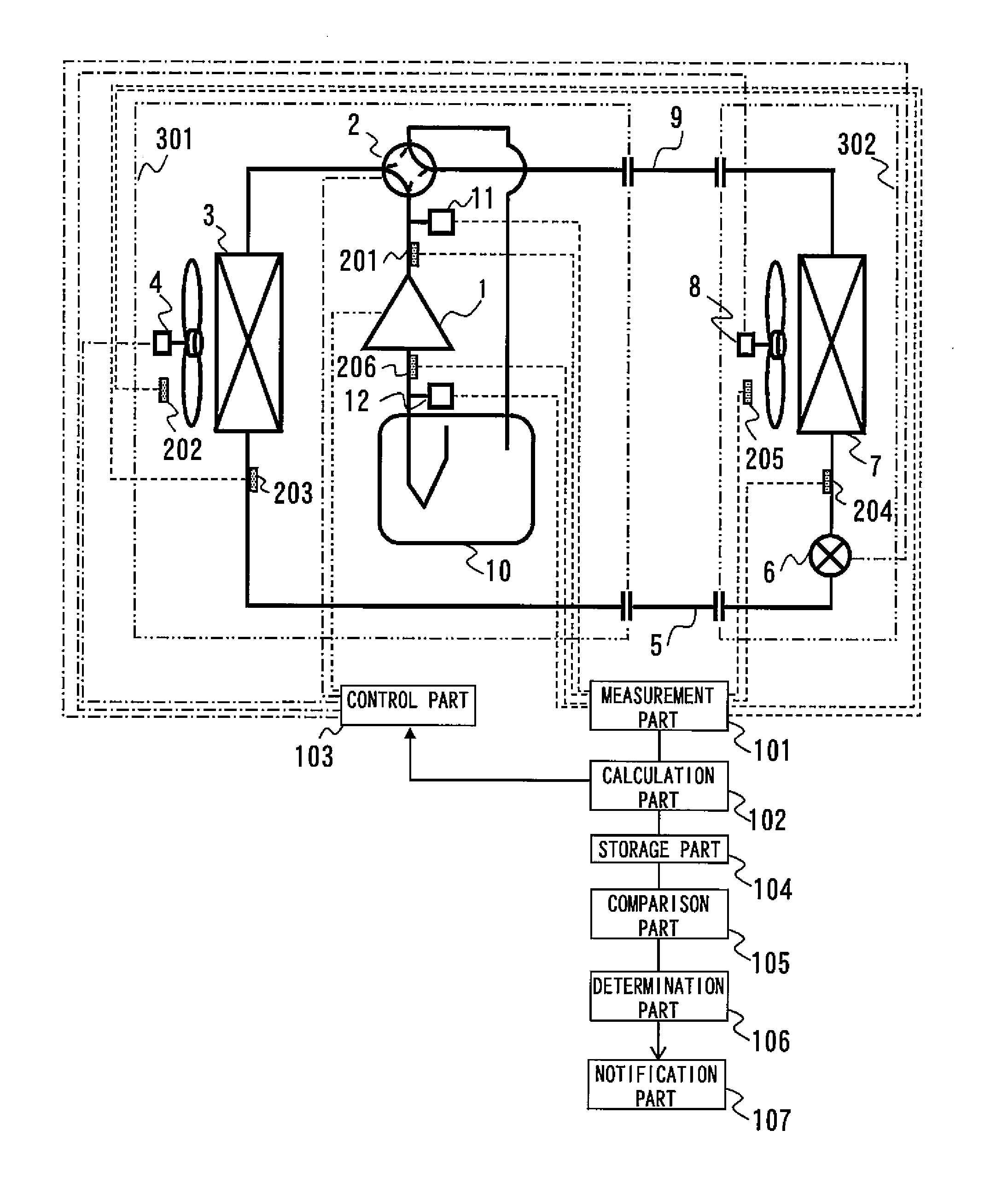
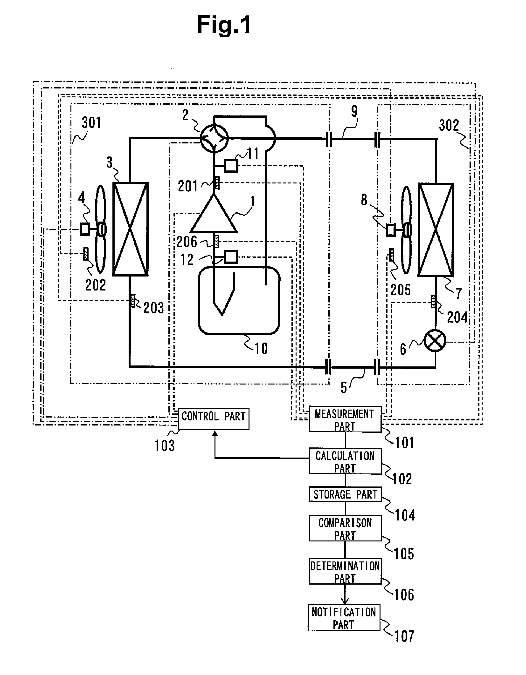
[0044]FIG. 1 is a schematic refrigerating circuit diagram of an air conditioning apparatus (refrigerating cycle apparatus) that employs a refrigerant amount determination system according to the first embodiment of the present invention. The air conditioning apparatus is an apparatus used for cooling / heating an indoor space as it performs vapor compression type refrigerating cycle operation.

[0045]The air conditioning apparatus is at least provided with a heat source unit 301, a utilization unit 302, and a liquid connection pipe 5 and gas connection pipe 9 which serve as refrigerant connection pipes to connect the heat source unit 301 and utilization unit 302.

[0046]More specifically, a vapor compression type refrigerating circuit of the air conditioning apparatus of this embodiment is constituted by connecting the heat source unit 301, utilization unit 302, liquid connection pipe 5, and gas connection pipe 9.

[0047]Examples of the refrigerant used by the air con...

embodiment 2

Device Configuration

[0223]The second embodiment of the present invention will now be described with reference to FIG. 10. The same structural portions as those of the first embodiment are denoted by the same numerals, and a detailed description thereof will be omitted.

[0224]FIG. 10 shows the refrigerating circuit of a refrigerating machine (refrigerating cycle apparatus) according to the second embodiment of the present invention. The refrigerating circuit of the second embodiment is constituted by removing the four-way valve 2 from the refrigerating circuit of the first embodiment, having a receiver 13 that reserves an excessive refrigerant and a supercooling coil 14 at the next stage of the outdoor heat exchanger 3, and providing an injection flow channel (distribution circuit) for the compressor 1 and an inflow channel for the indoor heat exchanger 7 at the next stage of the receiver 13 and supercooling coil 14. The injection flow channel is provided with a pressure reducing devi...

embodiment 3

Device Configuration

[0242]The third embodiment of the present invention will be described with reference to the drawings. The same structural portions as those of the first embodiment are denoted by the same numerals, and a detailed description thereof will be omitted.

[0243]FIG. 12 is a refrigerating circuit diagram of an air-cooling heat pump chiller apparatus that employs a refrigerant amount determination system according to the third embodiment of the present invention. The air-cooling heat pump chiller apparatus (refrigerating cycle apparatus) is an apparatus used to cool or heat water by carrying out vapor compression type refrigerating cycle operation.

[0244]This refrigerating circuit is provided with at least a compressor 1 which compresses a refrigerant, a four-way valve 2 which switches the refrigerant flowing direction, an outdoor heat exchanger 3 serving as a heat source side heat exchanger, a supercooling coil 17, a supercooling coil 19, pressure reducing devices 6, 16, ...


PUM


Abstract

A refrigerating cycle apparatus is obtained that can determine excess/shortage of a refrigerant amount in a refrigerating circuit at high precision even if a factor such as a heat exchanger whose refrigerant amount is difficult to calculate exists. The refrigerating cycle apparatus according to the present invention includes one heat source unit or more, one utilization unit or more, a refrigerating circuit constituted by the heat source unit and utilization unit, a storage part which stores an appropriate refrigerant amount of a refrigerant to be charged in the refrigerating circuit and a correction coefficient which corrects a liquid refrigerant amount such that calculation of the refrigerant amount of each constituent element of the refrigerating circuit is equal to the appropriate refrigerant amount, a measurement part which detects an operation state amount in each constituent element of the refrigerating circuit, a calculation part which calculates the refrigerant amount of each constituent element of the refrigerating circuit based on the operation state amount by using the correction coefficient, a comparison part which compares the appropriate refrigerant amount with a calculative refrigerant amount calculated by the calculation part, and a determination part which determines excess/shortage of the refrigerant amount charged in the refrigerating circuit based on a comparison result of the comparison part.

Description

TECHNICAL FIELD[0001]The present invention relates to a refrigerating cycle apparatus such as an air conditioning apparatus and, more particularly, to a function of determining the excess / shortage of the refrigerant amount by calculating the refrigerant amount in a refrigerating circuit, comparing the calculative refrigerant amount and an appropriate refrigerant amount, and performing correction so that the two values become equal. Specifically, the present invention relates to a function of determining the excess / shortage of the refrigerant amount in a refrigerating circuit in a refrigerating cycle apparatus constituted by connecting a compressor, a condenser, a pressure reducing device, and an evaporator.BACKGROUND ART[0002]An example of a conventional air conditioning apparatus includes a separate type air conditioning apparatus in which a heat source unit and a utilization unit are connected via a connection pipe to constitute a refrigerating circuit. Examples of the separate ty...

Claims


Application Information

Patent Timeline
Patent Type & Authority Applications(United States)
IPC IPC(8): F25B49/02F25B41/04F25D23/00
CPCF25B13/00F25B45/00F25B49/005F25B2313/0272F25B2313/02741F25B2345/001F25B2700/135F25B2400/13F25B2500/222F25B2700/04F25D2500/04F25B2700/133F25B2345/002
Inventor TAMAKI, SHOGOTANAKA, KOSUKEUNEZAKI, FUMITAKEITO, TAKUYAKOMATSU, KAZUHIRO
Owner MITSUBISHI ELECTRIC CORP
Why Eureka
Try Eureka