Flow Control System for a Micropump

Inactive Publication Date: 2011-12-22
PICOLIFE TECH
View PDF15 Cites 20 Cited by
  • Summary
  • Abstract
  • Description
  • Claims
  • Application Information

AI Technical Summary

Benefits of technology

[0034]Another object of the present disclosure is to provide, in combination with the other features and advantages disclosed herein, a flow control system for use with a micropump that prevents reverse flow or backflow, which is particularly important in medical applications.
[0035]An even further object of the present disclosure is to provide, in combination with the other fea

Problems solved by technology

Micropumps are one of the main components of these systems and are often the limiting factor for size, weight and cost.
However, the size of the electric motors necessary for delivering the desired forces prevents miniaturization below the 40-50 mm range.
This severely limits the scope of applications to large and bulky drug delivery systems.
However, the material cost of silicon and related fabrication issues burden its use.
However, the PDMS pumps described are based on expensive microfabrication techniques, which require costly equipment that utilizes an inherently slow process.
This limits the ability for manufacturers to mass-produce these types of pumps.
They were successful in reducing manufacturing costs but not to the point desired for disposable systems.
In the case of piezoelectric actuators, piezoelectric materials are expensive and they require high operating voltages.
This requires the use of specialized, expensive, and bulky electronics, which is especially difficult to incorporate in embedded applications.
In the case of electromagnetic actuators, an expensive and bulky coil is required inside the pump.
In both cases, electrodes and supply wiring are needed in the pump body itself, which increases the volume and price of the pump.
Unfortunately, the relatively high cost of micropumps today prevents disposable use, which strongly limits the scope of their applications.
This often leads to a lack of reproducibility and a lack of flow rate predictability.
As a result, the ability to supply precise flow rates and doses is severely impeded making them poorly suited for applications such as drug delivery.
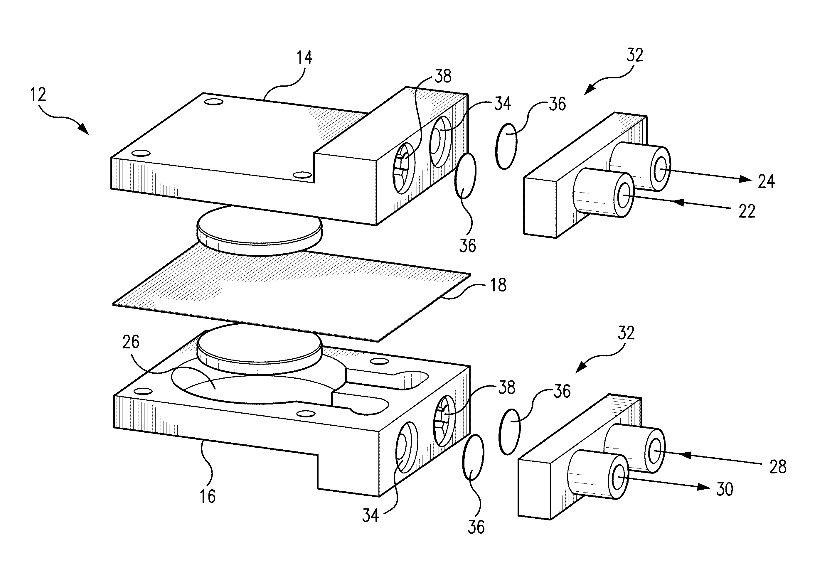
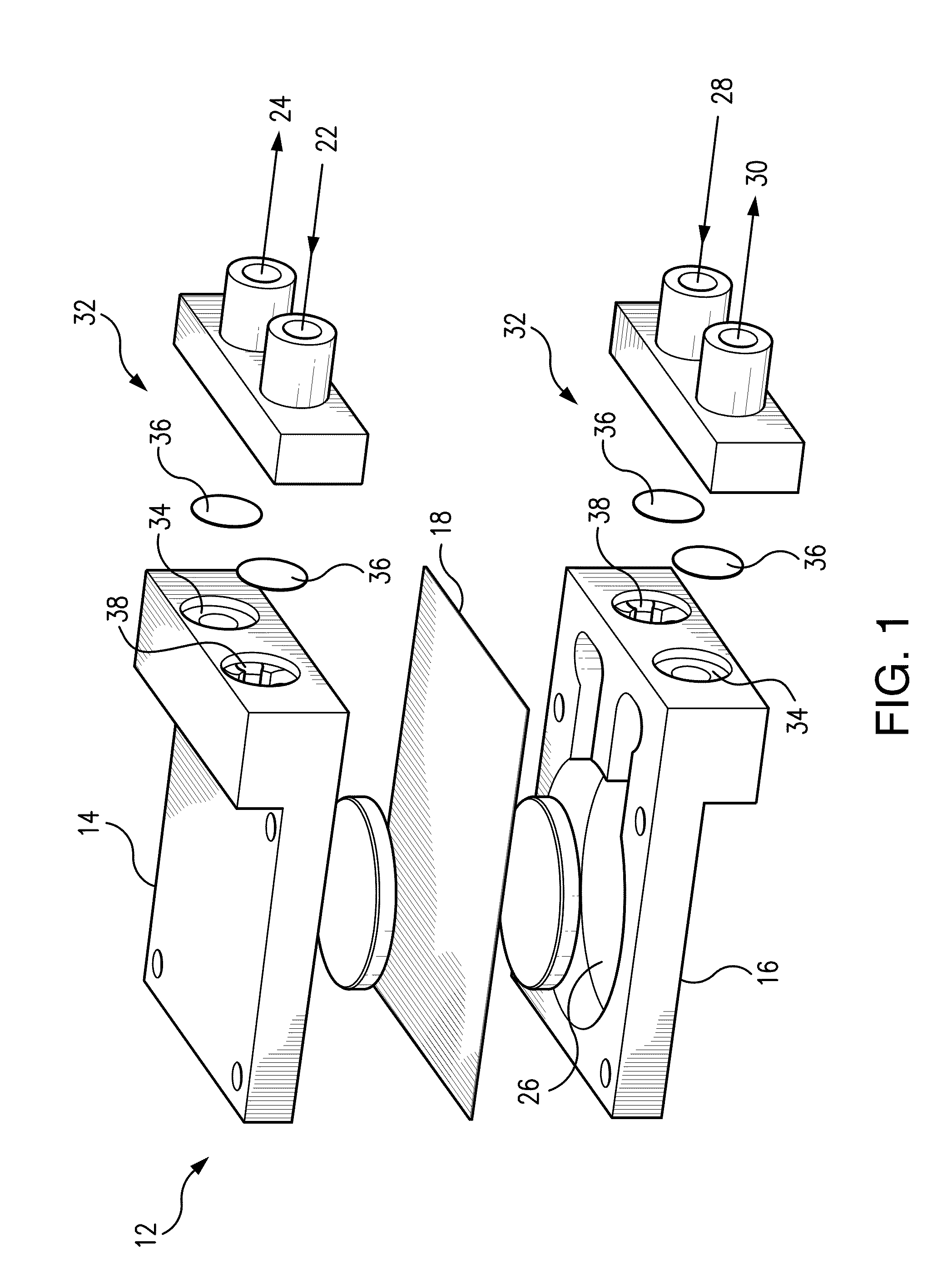
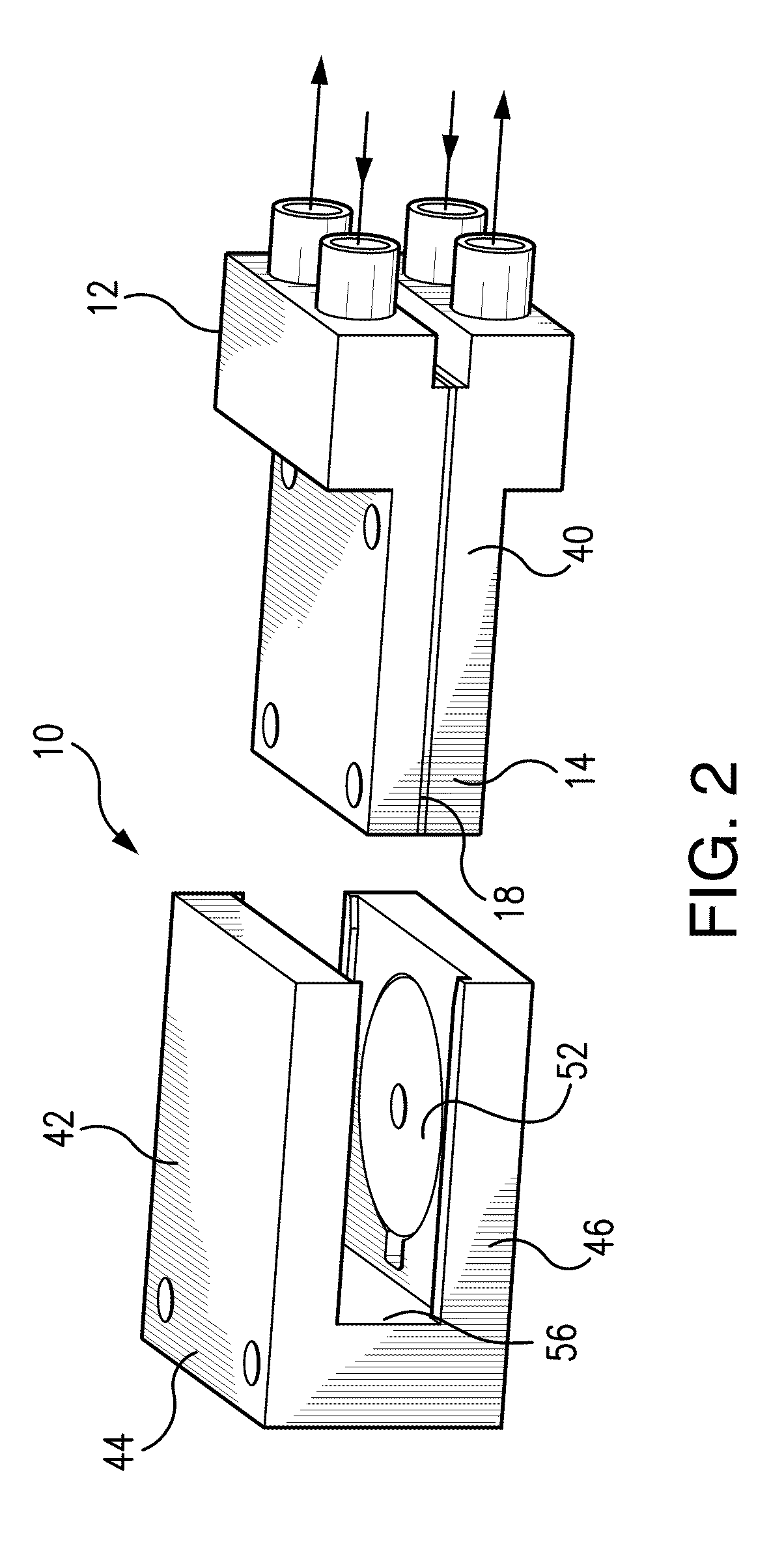
Thus, a problem associated with devices that precede the present disclosure is that they do not provide, in combination with the other features and a

Method used


Image

  • Flow Control System for a Micropump
  • Flow Control System for a Micropump
  • Flow Control System for a Micropump

Examples


Embodiment Construction

[0075]Referring now to FIGS. 1 and 2, the micropump 10 of the present disclosure includes a pump assembly 12 having a first pump body 14, a second pump body 16 and a flexible membrane 18 disposed therebetween. The first pump body 14 defines a first body flow path and includes a first chamber 20 (shown in FIG. 4). The first pump body 14 further includes a first inlet 22 and a first outlet 24 in fluid communication with the first chamber. Likewise, the second pump body 16 defines a second body flow path and includes a second chamber 26. The second pump body 16 further includes a second inlet 28 and a second outlet 30 in fluid communication with the second chamber 26.

[0076]Several proposed actuation mechanisms for micropumps have been reported already, mainly including piezoelectric, electrostatic, electromagnetic, and thermo-pneumatic and shape memory alloy, etc. The majority of the micropumps employ piezoelectric or electrostatic actuation, which operate at a relatively high frequenc...


PUM

PropertyMeasurementUnit
Fractionaaaaaaaaaa
Fractionaaaaaaaaaa
Fractionaaaaaaaaaa

Abstract

A flow control system is disclosed for use with a micropump for pumping a fluid to be administered through a catheter. The flow control system includes a first body portion, a membrane and a second body portion. The first body portion has a membrane-receiving inner surface, an inlet aperture in fluid communication with the micropump, and a mating surface disposed about the membrane-receiving inner surface and configured to mate with a mating surface of the second body portion. The membrane has a reinforcement annulus configured to be received by the first body portion membrane-receiving inner surface and a domed portion oriented to be movable from a closed position, in sealable communication with the inlet aperture, and an open position, in spaced apart relation from the inlet aperture. The membrane is oriented and sized to be biased in the closed position. The second body portion has a membrane-receiving inner surface, an outlet aperture configured to communicate with the catheter, and a mating surface disposed about the membrane-receiving inner surface and configured to mate with the mating surface of the first body portion. At least a portion of the membrane reinforcement annulus is positioned within the inner surface of the first body portion. The first body portion mating surface is positioned and maintained in sealed relation with the second body portion mating surface. Operation of the micropump causes the fluid to (a) flow from the micropump to the first body inlet aperture, (b) exert a pressure sufficient to move the membrane from the closed position to an open position, (c) flow around the membrane and through the second body outlet aperture and into the catheter.

Description

CROSS REFERENCE TO RELATED APPLICATIONS[0001]This application is a continuation-in-part of International Application No. PCT / US / 059020, filed Sep. 30, 2009, which is herein incorporated in its entirety and which in turn claims priority to U.S. provisional patent application Ser. No. 61 / 152,165, filed Feb. 12, 2009. This application also claims priority to U.S. provisional patent application Ser. No. 61 / 448,050, filed Mar. 1, 2011.FIELD OF THE INVENTION[0002]The present disclosure relates to a flow control system for a magnetically driven micropump for handling small fluid volumes. In particular, the present disclosure relates to a micropump including a magnetically actuated membrane to transfer fluids, and an innovative flow control system therefor utilizing a membrane designed particularly therefor.BACKGROUND OF THE INVENTION[0003]The present disclosure relates to a flow control system for a magnetically driven micropump for handling small fluid volumes. In particular, the present ...

Claims


Application Information

Patent Timeline
IPC IPC(8): F16K21/04
CPCY10T29/49996F04B43/043A61M5/16804A61M2205/0244A61M39/24A61M5/1422A61M5/14224A61M2039/2453Y10T137/7879Y10T137/86002Y10T137/86019
Inventor AMIROUCHE, FARIDCANTWELL, MATTHEW
Owner PICOLIFE TECH
Why Eureka
Try Eureka