Portable chargeable spray bottle

a spray bottle and charging technology, applied in the field of spray bottles, can solve the problems of waste of productive materials, easy to spill and leak, environmental pollution when thrown away, etc., and achieve the effects of saving costs, reducing resource waste, and convenient portability

Active Publication Date: 2011-12-22
DONGGUAN YIXIN MAGNETIC DISK
View PDF4 Cites 26 Cited by
  • Summary
  • Abstract
  • Description
  • Claims
  • Application Information

AI Technical Summary

Benefits of technology

[0043]With the abovementioned structures, the spray bottle is convenient for carrying and can be reused, thus reducing the waste of resources. The user can quickly charge the spray bottle through charging structure instead of throwing it away once the liquid in the bo...

Problems solved by technology

Though charging bottles with charging accessories appear in the market, they are complex, easy to spill and leak, and inconvenient.
The current spray bottles made from plastic or glass causes environmental pollution when they are thro...

Method used


Image

  • Portable chargeable spray bottle
  • Portable chargeable spray bottle
  • Portable chargeable spray bottle

Examples


embodiment 1

[0071] As shown in FIG. 4A and 4b, an exhaust hole 16 is equipped on the upper part of bottle 2. The exhaust hole 16 penetrates the side wall of bottle and is interconnected with the outside. When charging, the air inside the bottle 2 is compressed, resulting in the increase of pressure. The air inside the bottle 2 is exhausted via exhaust hole 16. Since the exhaust hole 16 is interconnected with the outside and is relatively small, it is easily blocked by dust and unwanted objects. The liquid in the bottle may flow out through exhaust hole 16 due to air pressure in an airplane or localities with high air pressure, so other embodiments will be stated as below.

embodiment 2

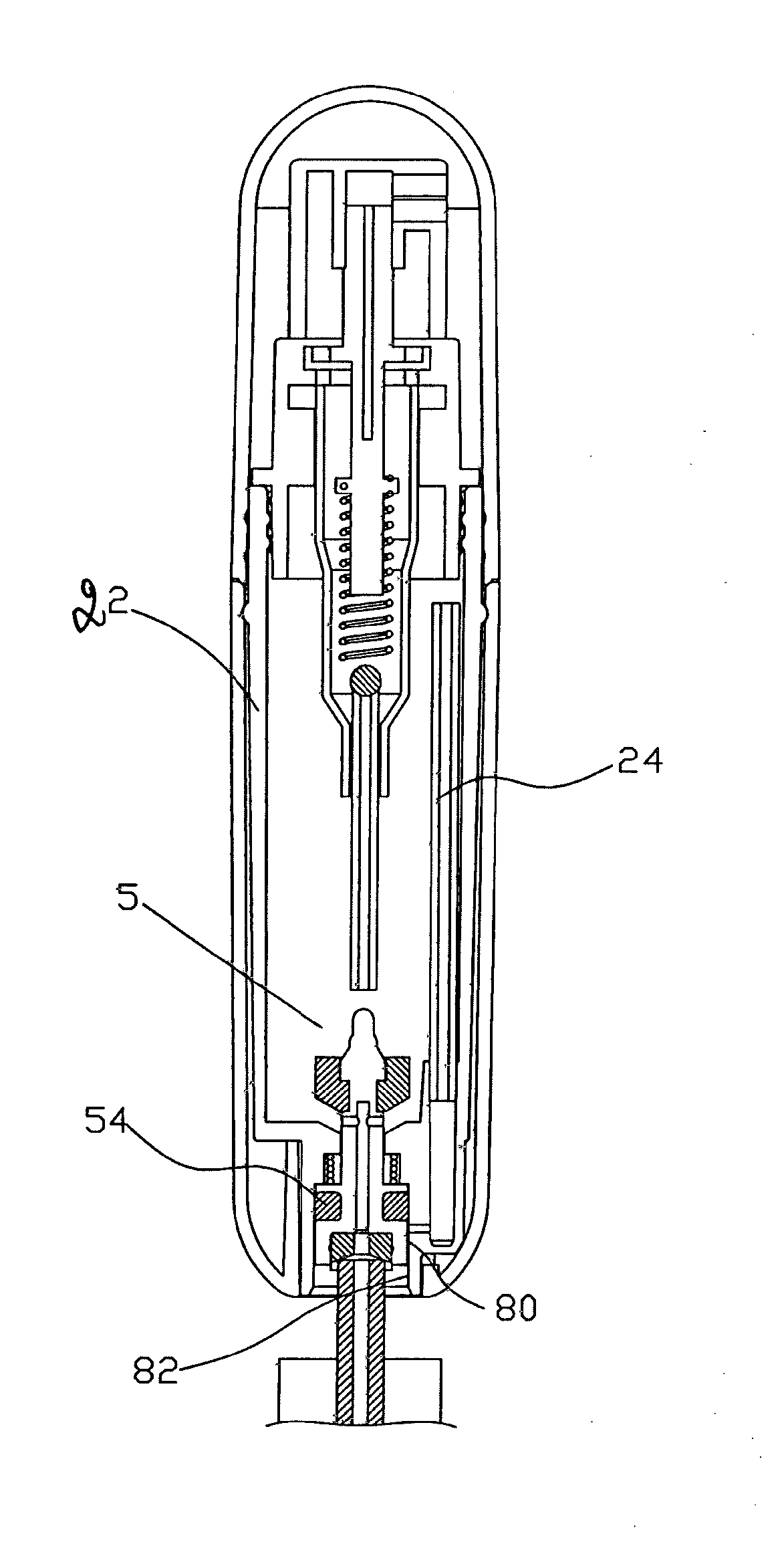
[0072] as shown in FIGS. 5 and 6, an exhaust hole 26 is equipped on the lower part of bottle 22 and corresponds to the groove of piston 5. An air duct 24 is interconnected with exhaust hole 26 and extends to the upper part of the bottle 22. Accordingly, the air in the bottle 22 can be exhausted through air duct 24 and exhaust hole 26. The dynamic sealing is formed by the second sealing ring 54 in the groove at the bottom of piston 5 and exhaust hole 26. That is, when charging, the second sealing ring 54 moves upwards driven by the piston and separates from exhaust hole 16, so that, the air duct 24 is directly connected with atmosphere; the second sealing ring 54 is compressed in the exhaust hole 26 in normal status, and the air duct 24 is blocked from atmosphere, thus forming sealing. Obviously, the simultaneous use can be carried out for Embodiment 1 and 2. That is to say, the exhaust hole 16 and 26 can coexist in the bottle 22.

[0073]Embodiment 3: as shown in FIGS. 9 and 10, Embodi...

embodiment 4

[0075] as shown in FIGS. 12 and 13, an exhaust hole 46 is equipped on the lower part of bottle 22, and an air duct 24 is interconnected with exhaust hole 46 and extends to upper part of bottle 22. A bead 58 is equipped at the bottom of exhaust hole 46 and on the compression spring 59, wherein the compression spring 59 is set on the lower part of bottle 22. Obviously, the simultaneous use can be carried out for Embodiment 1 and 4. That is to say, the exhaust hole 16 and 46 can coexist in the bottle 22.

[0076]As shown in FIG. 14, when a spray bottle 22 is charged, the nozzle of the external large bottle is aligned with liquid charging mouth 21, thus the opening of liquid charging passage 51 of piston is aimed at the nozzle of the external large bottle. Then the spray bottle 22 is pressed down to drive the piston 5 to move upwards and compress spring 56. Furthermore, the first sealing ring 53 on the piston 5 is separated from the sloped side wall 212 on the top of liquid charging mouth ...


PUM


Abstract

A portable chargeable spray bottle is disclosed comprising a body comprising an upper part and a lower part; a spray nozzle assembly equipped on the upper part, and a liquid charging structure placed at the bottom part. It is further comprises an exhaust structure comprising an exhaust hole penetrating the body, whereby exhaust air flow can escape via the exhaust hole to outside the bottle.

Description

CROSS-REFERENCE TO RELATED APPLICATION(S)[0001]This application is a continuation-in-part of PCT Patent Application No. PCT / CN2009 / 072347, filed Jun. 19, 2009, which is based upon Chinese Patent Application No. 20082026225.2, filed Dec. 26, 2008, the benefit of the priority of the filing dates of both patent applications being claimed herewith.BACKGROUND OF THE INVENTION[0002]1. Technical Field[0003]The present invention relates to a spray bottle which can carry and spray liquid, and more especially, to a portable chargeable spray bottle.[0004]2. Description of Related Art[0005]Currently, the well-known portable spray bottle comprises a nozzle assembly, a bottle and an enclosure. The majority of spray bottles are used only once and thrown away when the liquid is used up. Though charging bottles with charging accessories appear in the market, they are complex, easy to spill and leak, and inconvenient. The current spray bottles made from plastic or glass causes environmental pollution...

Claims


Application Information

Patent Timeline
IPC IPC(8): B65D83/42
CPCB05B11/0018B05B11/0097B05B11/0056B65D83/425B65D83/42B65D83/70B05B11/02B65D83/14B05B11/00442B65D83/207
Inventor HUI, YI MINGWANG, ZHI
Owner DONGGUAN YIXIN MAGNETIC DISK
Why Eureka
Try Eureka