Free Flow Spreader Device

a spreader device and free flow technology, applied in the direction of centrifugal wheel fertilisers, ways, constructions, etc., can solve the problems of limiting their usefulness, unable to provide even spread of material during operation, and difficult to evenly spread and even harmful, so as to prevent clinging or voids, improve material settling, and eliminate uneven material placement

Inactive Publication Date: 2011-12-22
WEEKS CHRISTOPHER
View PDF0 Cites 30 Cited by
  • Summary
  • Abstract
  • Description
  • Claims
  • Application Information

AI Technical Summary

Benefits of technology

[0016]It is therefore an object of the present invention to provide a new spreader device that provides the user a means for uniformly dispensing material from a hopper using a specifically designed hopper, an agitator attached to the hopper chute and a cone-shaped stopper for evenly gravity feeding material onto an impeller device for dispensation thereof.
[0017]Another object of the present invention is to provide a hopper design that incorporates a balloon shape that tapers in a curved fashion from the hopper fill to the hopper chute. The hopper is likewise comprised of an elastic, non-slip material to prevent cling

Problems solved by technology

They eliminate the need for a user to manually spread the material, which is time consuming, difficult to spread evenly and even harmful depending upon the specific material being spread.
Spreaders commonly used in the art share common drawbacks that limit their usefulness and cause problems during operation.
Most notably, these spreaders do not provide even spreading of material during operation, as clumps and void develop in material contained in the hopper.
This leads to a non-uniform distribution of flow from the hopper outlet to an impeller or similar spreading means.
This leads to a condition wherein the spreader is receiving a bulk inflow of material or material at a non-uniform rate.
The result is uneven distribution or dispensation of too much material in one area.
This can lead to losses in material, money and possibly damage to the agriculture in the affected location.
While this

Method used


Image

  • Free Flow Spreader Device
  • Free Flow Spreader Device
  • Free Flow Spreader Device

Examples


Embodiment Construction

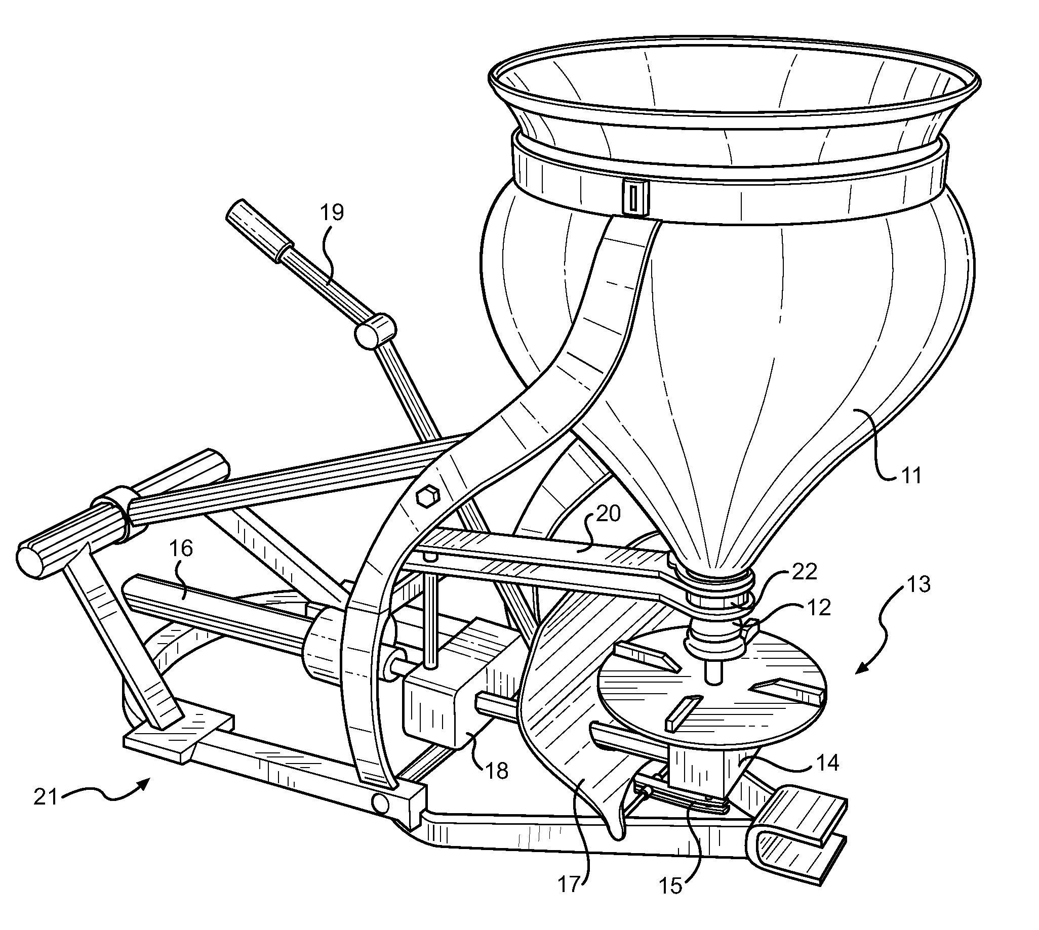
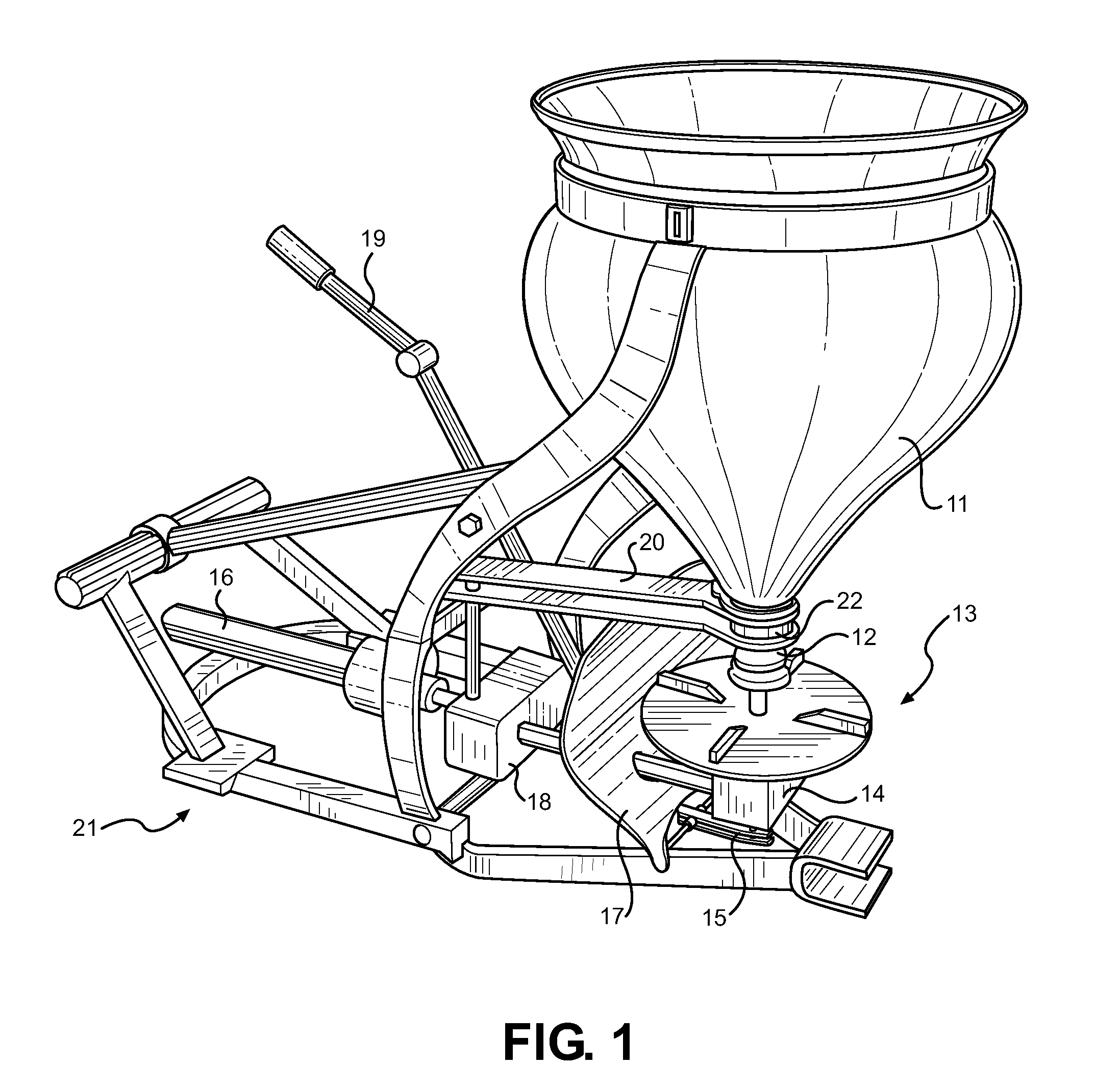
[0029]Referring now to FIG. 1, there is shown a perspective view of the preferred embodiment of the present invention. A balloon shaped hopper 11 attaches to a tractor pull frame 21. The base of the hopper terminates at a chute 22, while its upper includes an opening for filling its interior with material intended for spreading. The hopper 11 includes a curved taper that promotes improved gravity feeding of material through its chute 22 with reduced tendency of material to adhere or stick along its inner surface. A cone-shaped stopper 12 controls flow of material through the chute, as its vertical positioning is controlled by the user via a control handle 19. The stopper 12 can completely shut off the flow of material from the hopper 11 or modify its flow rate, depending upon its positioning relative to the chute 22. The control handle 19 connects to a positioning arm 15 below the impeller 13 for direct control of the stopper 22 position.

[0030]A rotating impeller device 13 provides ...


PUM


Abstract

Disclosed is an improved means for spreading solid or liquid agricultural products, ideally suited for use with a tractor or similar vehicle with an external power takeoff shaft. For solid agricultural products, a specially designed hopper is used in conjunction with a cone-shaped, flow control stopper and an outlet agitator for providing a uniform delivery of product onto a rotating impeller. A plurality of gearboxes provide motive distribution of power for the hopper outlet agitation and impeller, while a user-accessible handle controls the control stopper height within the hopper outlet, and thus controlling the flow rate from the hopper. For liquid products, a cylindrical hopper is provided, along with a pump and a plurality of hoses for drawing or recycling the liquid product. A rear-mounted spray rail is provided for dispensing the liquid product, while an accessory connection is provided for a user to manually distribute the product with an attachable spray gun device.

Description

CROSS REFERENCE TO RELATED APPLICATION[0001]This application claims the benefit of U.S. Provisional Application No. 61 / 357,118 filed on Jun. 22, 2010, entitled “Free Flow Spreader.”BACKGROUND OF THE INVENTION[0002]1. Field of the Invention[0003]The present invention relates to tractor-driven, agricultural material spreader devices. More specifically, the present invention pertains to devices for spreading liquid or solid material, and an improved means of evenly dispensing and broadcasting the same.[0004]2. Description of the Prior Art[0005]Agricultural and lawn care spreaders are well described in the art. These devices provide a means for distributing liquid, solid or moistened material as they are operated, in either a broadcast, drop or spray manner. The size and sophistication of these devices are dependent upon intended application and intended coverage area. The means for distribution, means for motive power and intended product are likewise diverse. Typical spreaders range f...

Claims


Application Information

Patent Timeline
IPC IPC(8): A01C23/00A01C3/06A01C19/00A01C17/00
CPCA01C17/001A01C15/006
Inventor WEEKS, CHRISTOPHER
Owner WEEKS CHRISTOPHER
Why Eureka
Try Eureka