Television set and speaker system

a technology of speaker system and television set, which is applied in the direction of television system, selective content distribution, gain control, etc., can solve the problems of deteriorating convenience and increasing costs

Inactive Publication Date: 2011-12-22
FUNAI ELECTRIC CO LTD
View PDF26 Cites 12 Cited by
  • Summary
  • Abstract
  • Description
  • Claims
  • Application Information

AI Technical Summary

Benefits of technology

[0009]It is an object of the present invention to provide a television set and a speaker system in compliance with a serial communication standard for digitally transferring audio data, such as S / PDIF, which, while suppressing a cost increase, allow the television set and a speaker device with a built-in amplifier to be operated using a single remote controller and thus provide a high degree of convenience.
[0011]According to this configuration, operating an operation tool on a single remote controller allows a predetermined function to be effected in the television set and the speaker device with the built-in amplifier, and thus a high degree of user's convenience is provided. Furthermore, since a control code is transmitted using a serial communication standard for digitally transferring audio, it is possible to achieve a link function without the need to additionally include any component based on a standard different from that standard and thus can suppress a cost increase.
[0013]Furthermore, in either of the above-described configurations, the control code transmission unit may transmit the control code for a given period of time. This configuration allows secure transmission of the control code to be confirmed in the speaker device with the built-in amplifier.

Problems solved by technology

In such a conventional speaker system made up of a television set and a sound bar, however, the television set and the sound bar are accompanied with dedicated remote controllers, respectively, requiring them to be operated using their respective dedicated remote controllers, which deteriorates convenience and thus has been problematic.
This, however, would require that, in addition to the above-described S / PDIF terminal, a component for establishing linkage such as an IR terminal or an HDMI (High-Definition Multimedia Interface) terminal be additionally included, which incurs a cost increase and thus has been problematic.

Method used


Image

  • Television set and speaker system
  • Television set and speaker system
  • Television set and speaker system

Examples


Embodiment Construction

[0025]Hereinafter, a description is made of an embodiment of the present invention with reference to the appended drawings. The following description uses, as an example, a speaker system made up of a television set capable of receiving digital broadcasts and a sound bar.

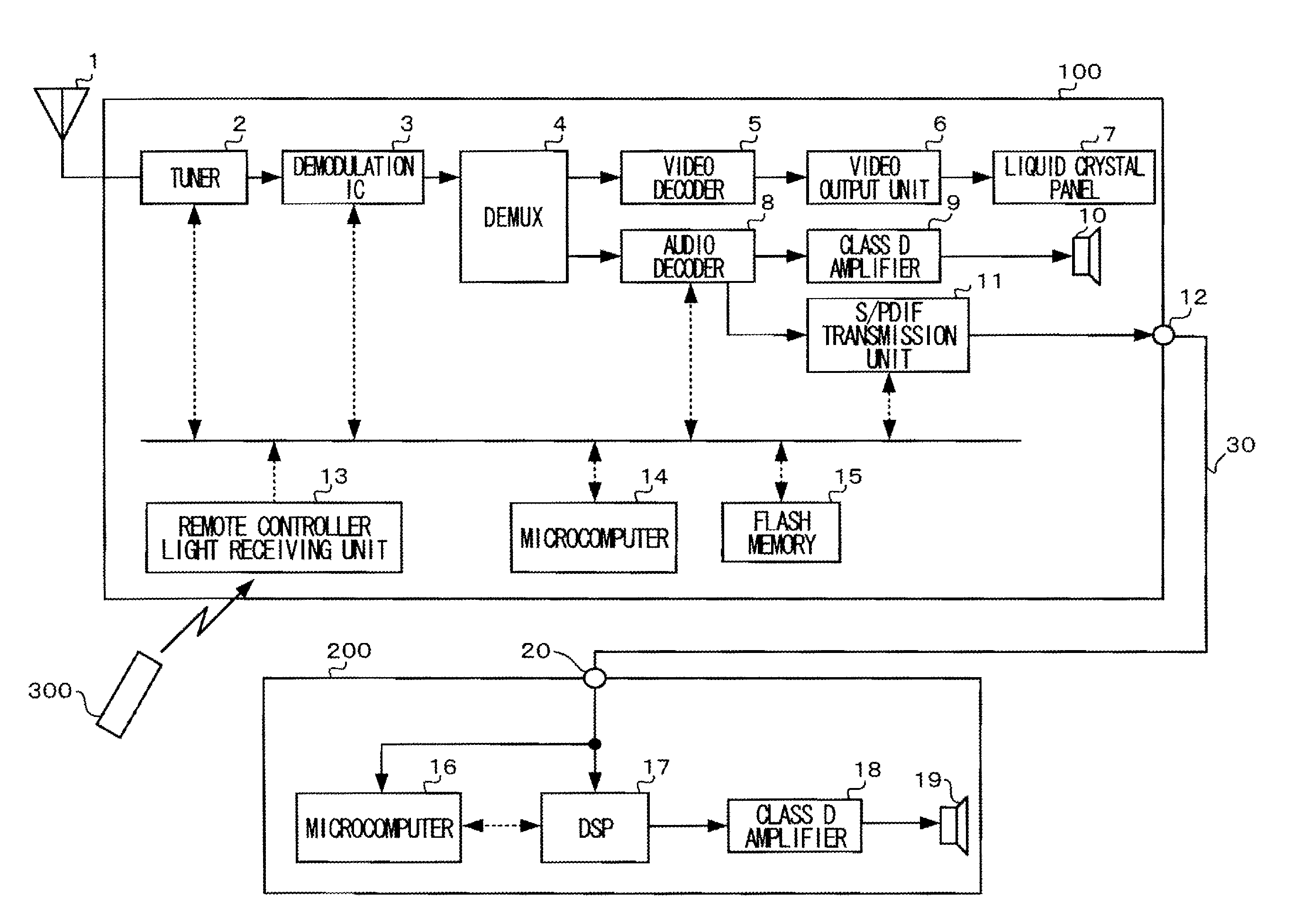
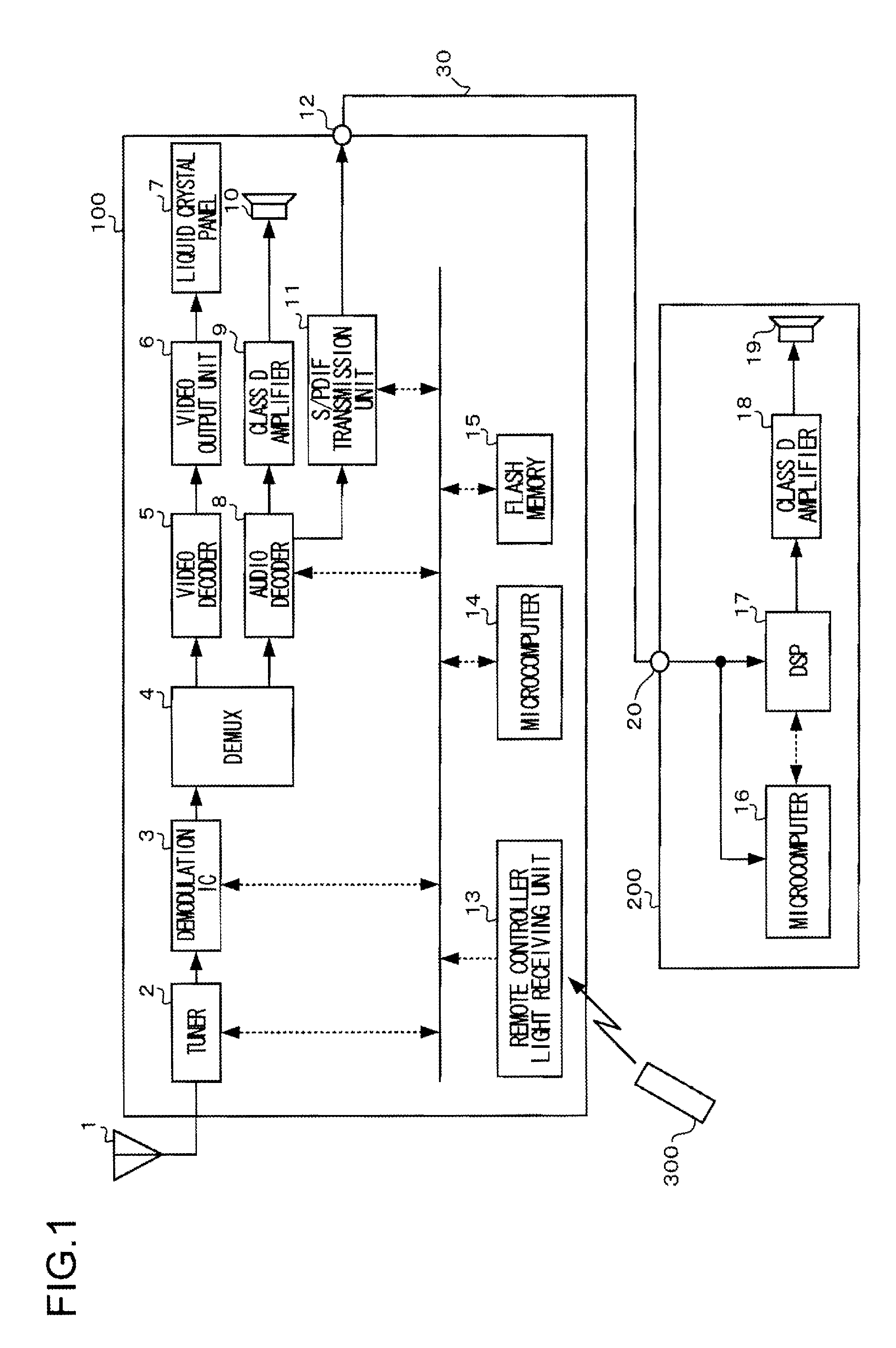
[0026]FIG. 1 is a diagram showing a schematic configuration of a speaker system according to one embodiment of the present invention. The speaker system of the present invention is made up of a television set 100 capable of receiving digital broadcasts and a sound bar 200 that is a speaker device with a built-in amplifier.

[0027]The television set 100 includes a tuner 2, a demodulation IC 3, a DEMUX (demultiplexer) 4, a video decoder 5, a video output unit 6, a liquid crystal panel 7, an audio decoder 8, a class D amplifier 9, a speaker 10, an S / PDIF transmission unit 11, an S / PDIF terminal 12, a remote controller light receiving unit 13, a microcomputer 14, and a flash memory 15. An antenna 1 is connected to the tun...


PUM


Abstract

A television set that transmits in a format based on a serial communication standard for digitally transferring audio, audio data to a speaker device with a built-in amplifier. The television set includes a control code transmission unit that, when an operation tool for effecting a predetermined function of the television set is operated on a remote controller, transmits in the format based on the serial communication standard, a control code corresponding to the predetermined function to the speaker device with the built-in amplifier.

Description

[0001]This application is based on Japanese Patent Application No. 2010-138876 filed on Jun. 18, 2010, the contents of which are hereby incorporated by reference.BACKGROUND OF THE INVENTION[0002]1. Field of the Invention[0003]The present invention relates to a link function between a television set and a speaker device with a built-in amplifier.[0004]2. Description of Prior Art[0005]A speaker system is made up of a television set and a speaker device with a built-in amplifier connected to the television set, and various types of such systems have conventionally been developed (see, for example, Japanese Unexamined Patent Application Publication (Translation of PCT Application) No. 2007-052625). Particularly in recent years, a so-called sound bar that is a speaker device with a built-in amplifier having a bar shape in appearance has come into widespread use.[0006]Furthermore, the television set and above-described sound bar of recent years each often include an S / PDIF (Sony / Philips D...

Claims


Application Information

Patent Timeline
Patent Type & Authority Applications(United States)
IPC IPC(8): H04N5/44
CPCH03G1/02H03G3/348H04N5/4403H04N21/43632H04R1/028H04R2430/01H04R2499/15H04N5/60H04N21/42204
Inventor TAKAHASHI, HIRONOBU
Owner FUNAI ELECTRIC CO LTD
Why Eureka
Try Eureka