

Light control film
a technology of light control and film, applied in the field of light control film, can solve the problems of difficult sealing of suspension, difficulty in keeping up the gap, and difficulty in putting in the initial light control device to be used in practice, and achieve the effect of stable light control function and high adhesiveness
- Summary
- Abstract
- Description
- Claims
- Application Information
AI Technical Summary
Benefits of technology
Problems solved by technology
Method used
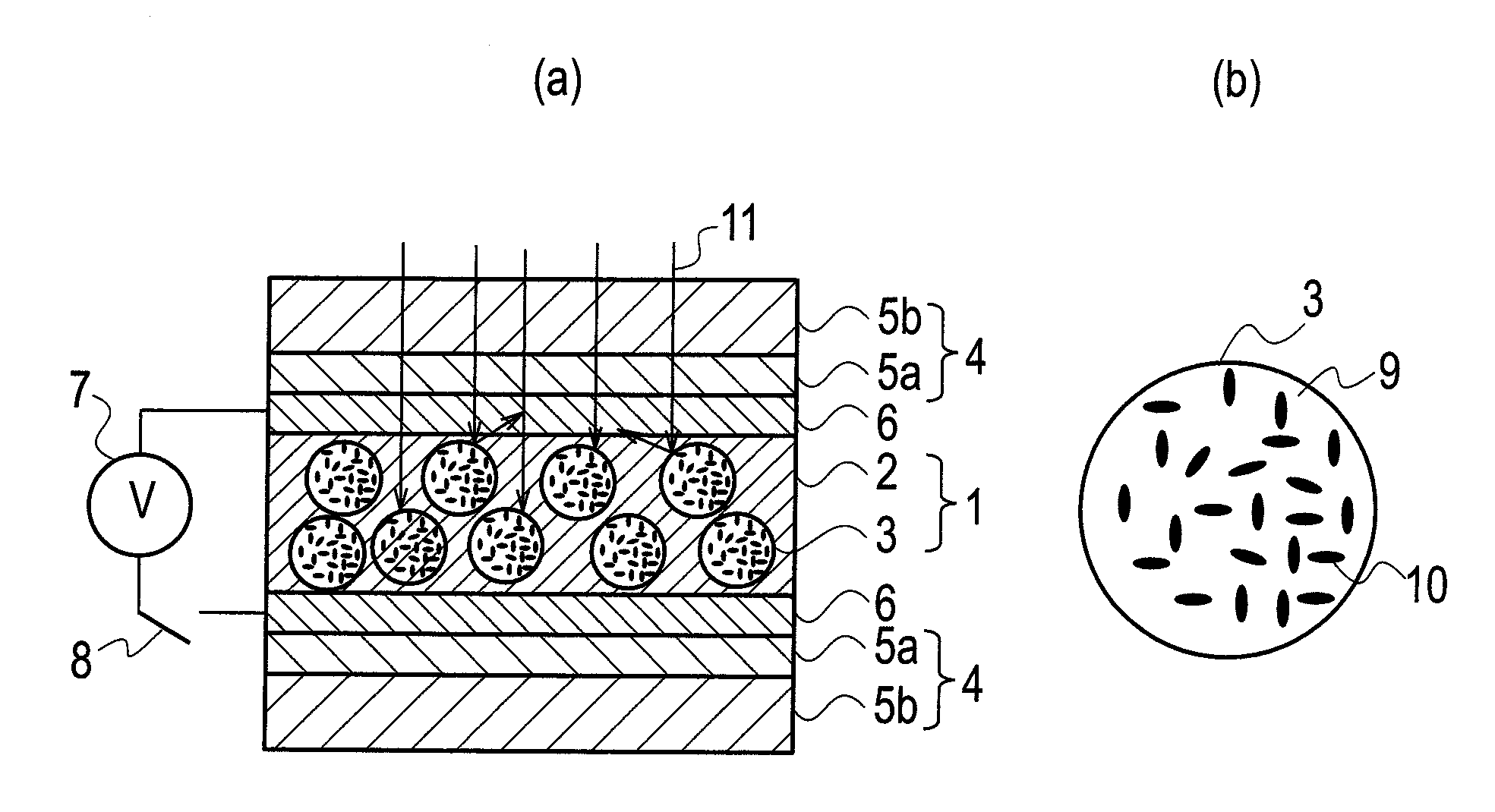
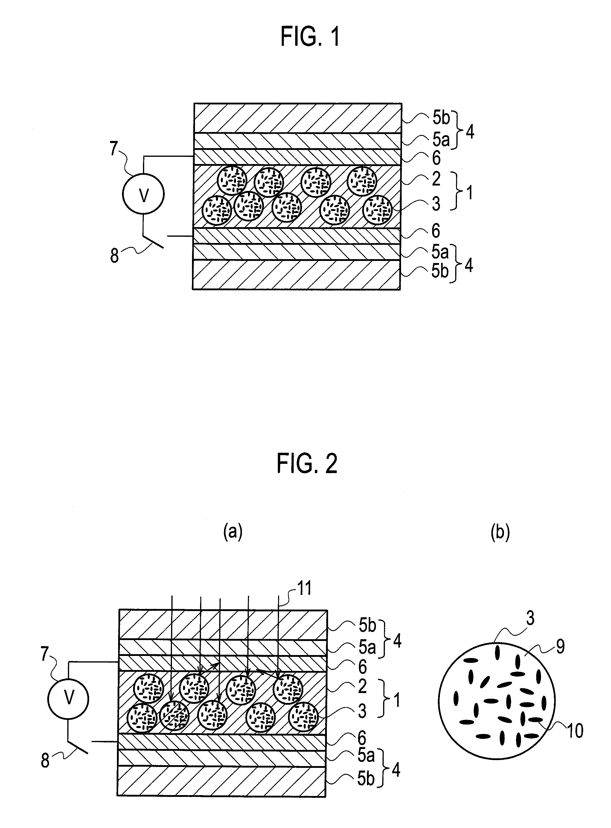
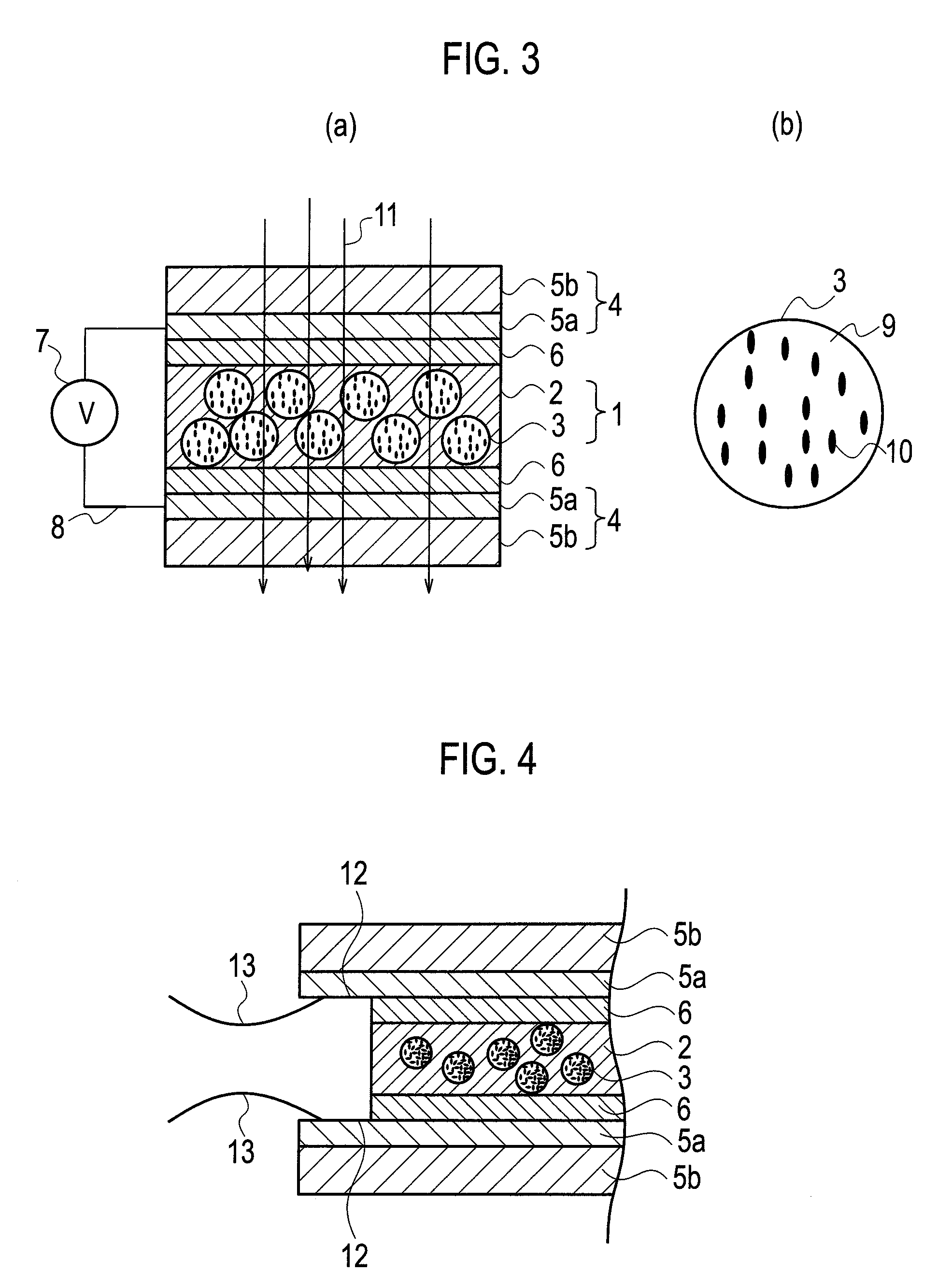
Image

Examples
example 1
[0171]The light control suspension yielded in the item (Production example of a light control suspension), the amount of which was 2.5 g, was added to 10 g of the energy-beam-curable silicone resin yielded in the item (Production example of an energy beam curable silicone resin), 0.2 g of bis(2,4,6-trimethylbenzoyl)phenylphosphine oxide (Ciba Specialty Chemicals Inc.) as a photopolymerization initiator, and 0.3 g of dibutyltin dilaurate as a coloration inhibitor, and then the components were mechanically mixed with each other for 1 minute to produce a light control material.
[0172]Separately, an applicator method was used under a condition that the gap (used therefor) was 10 μm to apply, as a solution at the time of primer-layer-formation, a dispersion liquid wherein 1,6-hexanediol diacrylate (trade name: LIGHT ACRYLATE 1,6HX-A, manufactured by Kyoeisha Chemical Co., Ltd.), ZrO2, and methyl isobutyl ketone were mixed with each other to give proportions of 1.0% by mass, 5.0% by mass, ...
example 2
[0188]A light control film was produced and then the various measurements were made thereabout in the same way as in Example 1 except that: an applicator method was used under a condition that the gap was 10 μm to apply, as the solution at the time of the primer-layer-formation, a liquid dispersion in which 1,6-hexanediol diacrylate (trade name: LIGHT ACRYLATE 1,6HX-A, manufactured by Kyoeisha Chemical Co., Ltd.), ZrO2 and methyl isobutyl ketone were mixed with one another to give proportions of 1.0% by mass, 1.0% by mass and 98% by mass, respectively, onto the entire surface of the transparent electroconductive film of each of the transparent electroconductive resin substrates; and the workpiece was dried at 50° C. for 30 seconds, 60° C. for 30 seconds, and 70° C. for 1 minute, and then irradiated with UV at 1000 mJ / cm2 (from a metal halide lamp) to photocure the resultant, thereby forming each primer layer. The results are shown in Table 1. At this time, a photopolymerization init...
example 3
[0191]A light control film was produced and then the various measurements were made thereabout in the same way as in Example 1 except that: an applicator method was used under a condition that the gap was 10 μm to apply, as the solution at the time of the primer-layer-formation, a liquid dispersion in which 1,6-hexanediol diacrylate (trade name: LIGHT ACRYLATE 1,6HX-A, manufactured by Kyoeisha Chemical Co., Ltd.), ITO and methyl isobutyl ketone were mixed with one another to give proportions of 1.0% by mass, 1.0% by mass and 98% by mass, respectively, onto the entire surface of the transparent electroconductive film of each of the transparent electroconductive resin substrates; and the workpiece was dried at 50° C. for 30 seconds, 60° C. for 30 seconds, and 70° C. for 1 minute, and then irradiated with UV m at 1000 mJ / cm2 (from a metal halide lamp) to photocure the resultant, thereby forming each primer layer. The results are shown in Table 1. At this time, a photopolymerization ini...
PUM
| Property | Measurement | Unit |
|---|---|---|
| particle diameter | aaaaa | aaaaa |
| thickness | aaaaa | aaaaa |
| optical density | aaaaa | aaaaa |
Abstract
Description
Claims
Application Information