Pulse width modulation communication system

a communication system and pulse width technology, applied in the direction of pulse technique, digital transmission, transmission, etc., can solve the problems of reduced responsiveness of sensor output value, reduced precision of digital signal produced through analog-to-digital conversion, and increased cost of dedicated circuits, so as to achieve low cost

Active Publication Date: 2011-12-22
DENSO CORP
View PDF2 Cites 27 Cited by
  • Summary
  • Abstract
  • Description
  • Claims
  • Application Information

AI Technical Summary

Benefits of technology

[0028]It is therefore an object of the present invention to provide a PWM communication system, which can perform high-precision multiplex communication, at a low cost.

Problems solved by technology

It is likely that the precision in digital signals produced through the analog-to-digital conversion may be degraded due to an adverse effect of noises convoluted to the ground line.
However, when the number of data sampling times is increased in order to improve the noise removing performance of the digital filter in the ECU, the responsiveness of a sensor output value may be degraded.
The inclusion of the dedicated circuit increases costs.
As a result, cost is increased due to the inclusion of the dedicated circuit.
Therefore, the technology is not satisfactory for multiplex communication.
The technology in the patent document 3 addresses a problem that a communication time is long and high-speed communication is hard to do.
Another problem of the technology in the patent document 3 is that, since modulating or demodulating processing is performed using a pulse-width modulator or a pulse-width demodulator, an error is caused in the modulating or demodulating processing.
In addition, according to the technology in the patent document 3, since special circuits such as the pulse-width modulator and pulse-width demodulator and an ac-coupled amplifier have to be included, a cost is increased due to the inclusion of the special circuits.
The technology in the non-patent document 1 addresses a problem that, since numerous pulses are needed to communicate all data items, the communication time is long and high-speed communication is hard to do.

Method used


Image

  • Pulse width modulation communication system
  • Pulse width modulation communication system
  • Pulse width modulation communication system

Examples


first embodiment

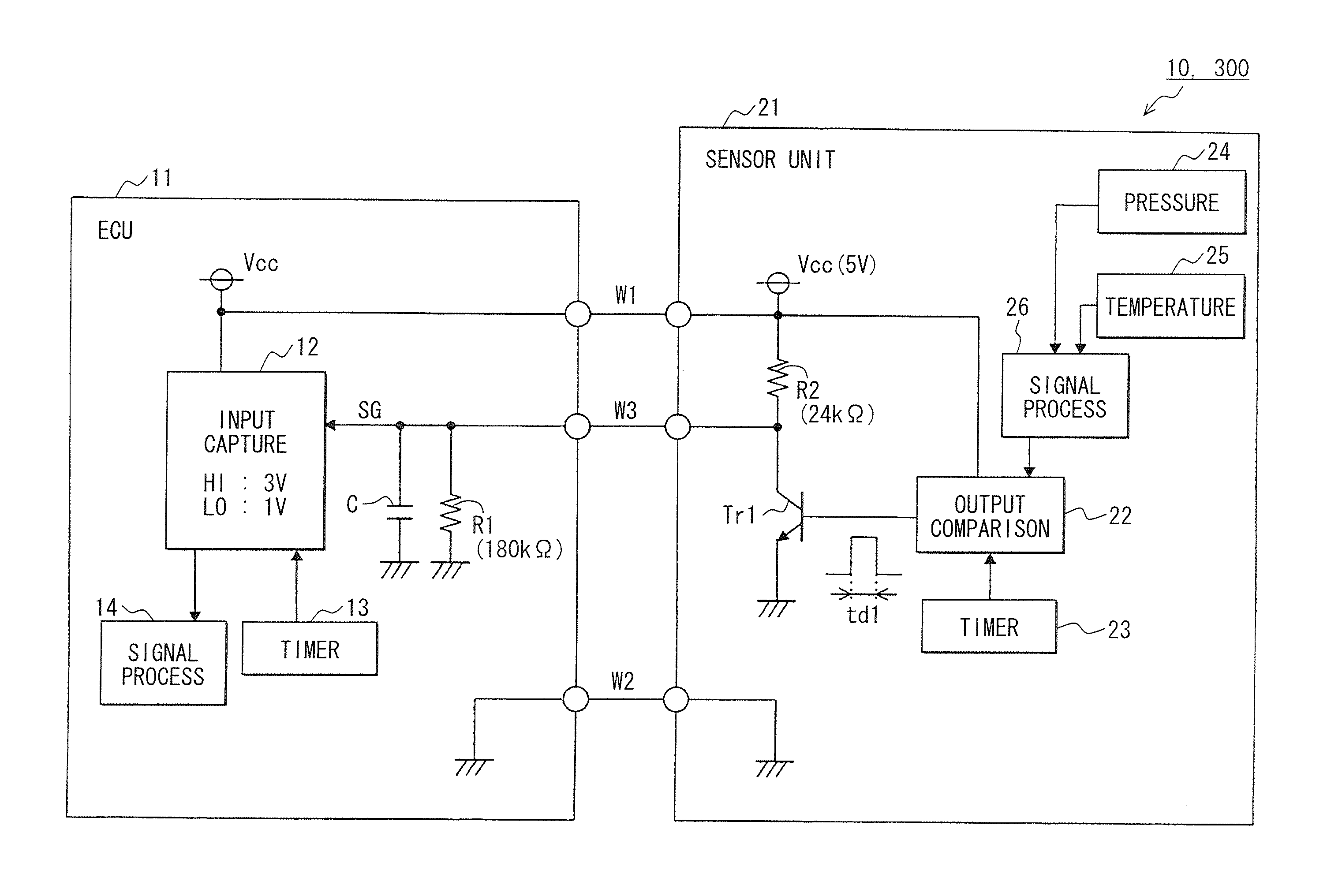
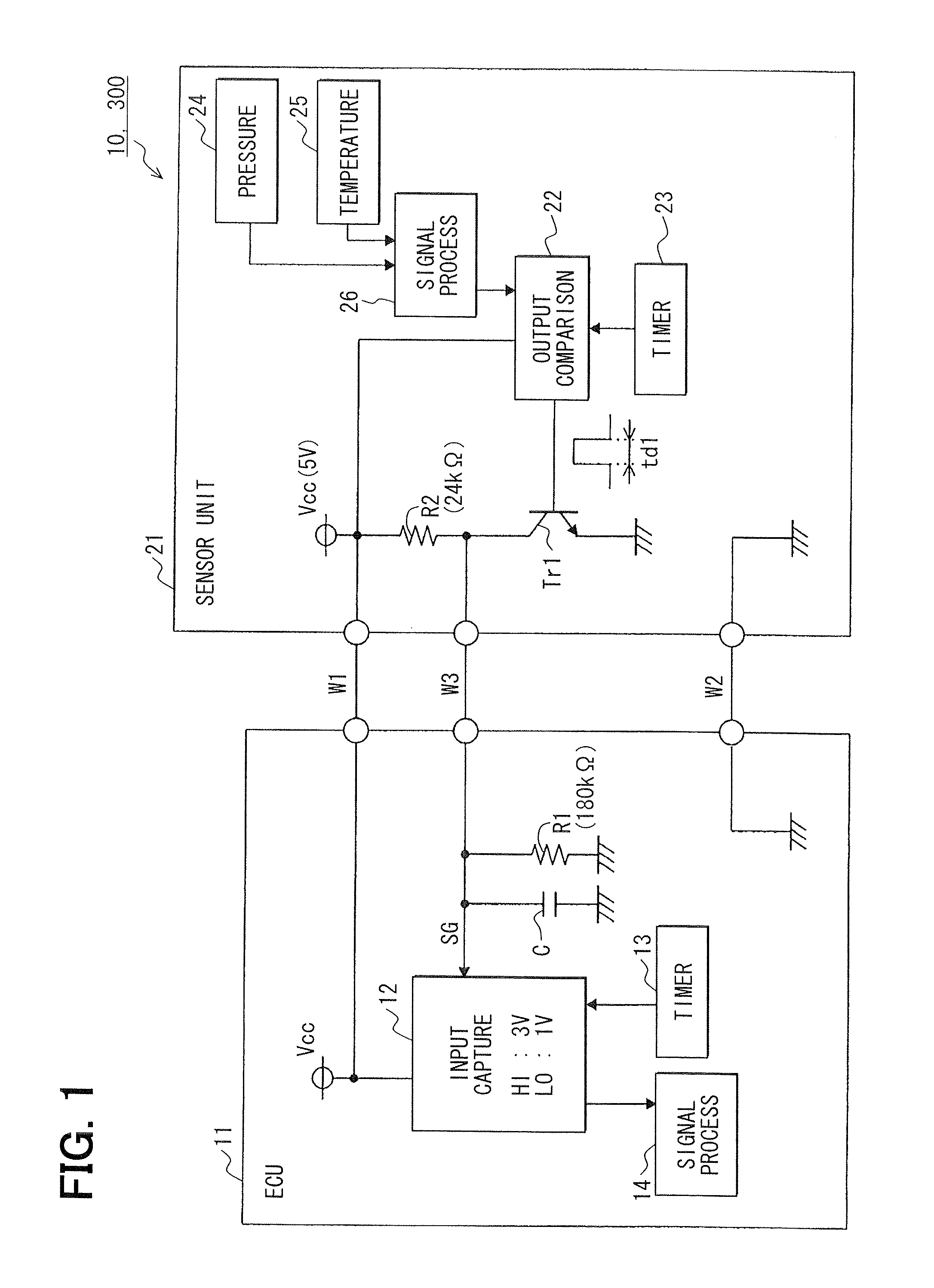
[0056]Referring to FIG. 1, a PWM communication system 10 in accordance with a first embodiment includes an ECU 11 provided as a receiving device, a sensor unit 21 provided as a transmitting device, and wiring harnesses W1 to W3 that connect the ECU 11 and sensor unit 21, and is mounted in a vehicle.

[0057]The ECU 11 includes an input capture (IPC) circuit 12, a timer circuit 13, a signal processing circuit 14, a capacitor C, and a resistor R1, and has a microcomputer (not shown) that operates in a 32-bit architecture.

[0058]The sensor unit 21 includes an output comparison (OC) circuit 22, a timer circuit 23, a pressure sensor 24, a temperature sensor 25, a signal processing circuit 26, an npn transistor Tr1, and a resistor R2. The pressure sensor 24 and the temperature sensor 25 are integrated into a single body.

[0059]The wiring harness W1 of positive power lines is coupled to a positive terminal of an onboard battery (not shown), has a positive power Vcc applied thereto, and feeds th...

second embodiment

[0173]Referring to FIG. 8, a PWM communication system 100 of a second embodiment includes an ECU 101, a sensor unit 102, and wiring harnesses W1 to W3 that link the ECU 101 and sensor unit 102, and is mounted in a vehicle.

[0174]The sensor unit 102 includes an output comparison circuit 22, a timer circuit 23, npn transistors Tr1 and Tr2, resistors R2 and R5, a pressure sensor 24, a temperature sensor 25, a signal processing circuit 26, and other sensors 103 and 104. The four sensors 24, 25, 103 and 104 are integrated.

[0175]The sensor 103 detects an appropriate object of detection of the vehicle (for example, an illuminance or an inclination of the vehicle), and produces a sensor output value of an analog value proportional to the result of the detection.

[0176]The sensor 104 detects an object of detection for use in correcting the sensor output value of the sensor 103, and produces a sensor output value of an analog signal proportional to the result of the detection.

[0177]The relation...

third embodiment

[0215]Referring to FIG. 10, a PWM communication system 200 in accordance with a third embodiment includes an ECU 101, a sensor unit 201, and wiring harnesses W1 to W3 that link the ECU 101 and sensor unit 201, and is mounted in a vehicle.

[0216]The sensor unit 201 includes an output comparison circuit 22, a timer circuit 23, npn transistors Tr1, Tr2 and Tr3, resistors R2, R5 and R6, a pressure sensor 24, a temperature sensor 25, a signal processing circuit 26, and other sensors 103 and 104. The four sensors 24, 25, 103 and 104 are integrated.

[0217]The output comparison circuit 22 operates, similarly to that in the first embodiment, according to a timer clock produced by the timer circuit 23.

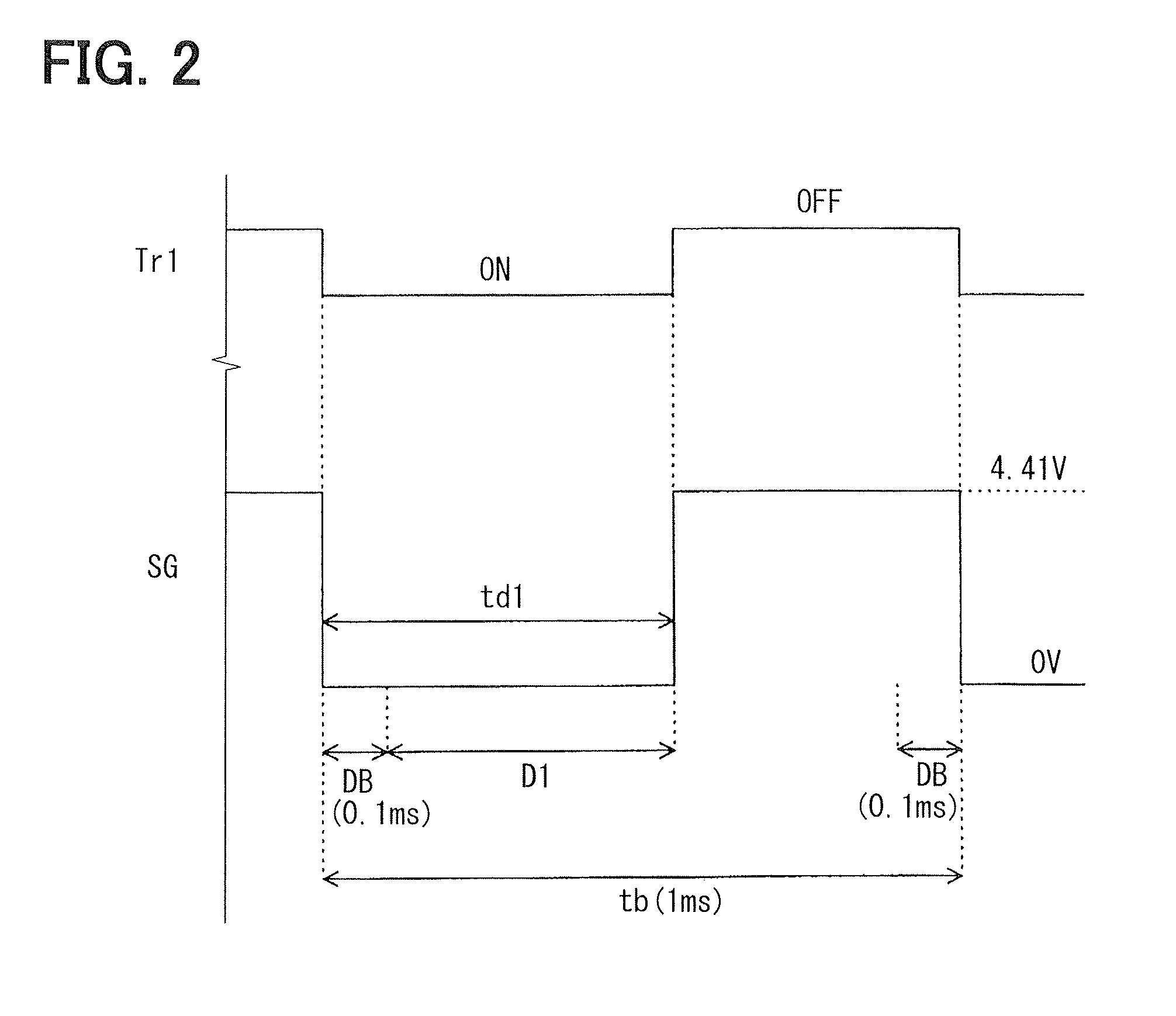
[0218]The output comparison circuit 22 then produces a first PWM signal, which has a duty time td1, on the basis of a digital signal representing the sensor output values of the respective sensors 24 and 25 and being produced by the signal processing circuit 26, and applies the PWM signal to the g...


PUM


Abstract

In a PWM communication system, a sensor unit transmits as reference pulses transmission signals, which exhibit duty cycles of 100% and 0%, respectively, prior to transmission of a transmission signal, which has data items compressed thereinto by a signal processing circuit. An input capture circuit of an ECU measures the duty time and the PWM cycle of the transmission signal according to a timer clock of a timer circuit. A signal processing circuit of the ECU produces a duty cycle correction factor k based on the measured duty times and PWM cycles of the reference pulses, produces receiving data based on the duty time and the PWM cycle of the transmission signal, and the duty cycle correction factor, and separates the receiving data into sensor output values of a pressure sensor and a temperature sensor.

Description

CROSS REFERENCE TO RELATED APPLICATION[0001]This application is based on and incorporates herein by reference Japanese patent application No. 2010-137495 filed on Jun. 16, 2010.FIELD OF THE INVENTION[0002]The present invention relates to a pulse width modulation (PWM) communication system.BACKGROUND OF THE INVENTION[0003]Patent document 1 (JP 2008-180596A, US 2008 / 0174450) discloses a PWM output type sensor circuit that outputs a PWM output signal, which has a pulse width associated with a value of a physical quantity, as information concerning the physical quantity.[0004]Patent document 2 (JP H06-284100) discloses a technology implemented in a multiplex communication method, in which plural analog signals that should be transmitted are pulse-width modulated and then time-division multiplexed, the multiplexed pulse width-modulated signals are transmitted over a sole transmission line, the signals are received over the transmission line in order to detect synchronous information, and...

Claims


Application Information

Patent Timeline
Patent Type & Authority Applications(United States)
IPC IPC(8): H03K7/08
CPCH04L25/4902H03K7/08
Inventor SAWAOKA, HIDEOMAKINO, YASUAKIMATSUOKA, TOSHIHIKO
Owner DENSO CORP
Why Eureka
Try Eureka