Spinal Facet Bone Screw System

a screw system and spine technology, applied in the field of spine devices, can solve the problems of enlargement of joints, cartilage thinning or disappearing, wear or degeneration of many people,

Inactive Publication Date: 2011-12-22
LIFE SPINE INC
View PDF27 Cites 26 Cited by
  • Summary
  • Abstract
  • Description
  • Claims
  • Application Information

AI Technical Summary

Benefits of technology

[0012]The present invention is a spinal facet bone screw system which, during installation, provides tactile feedback to the

Problems solved by technology

Facet joints are in almost constant motion with the spine and quite commonly simply wear out or become degenerated in many people.
When facet joints become worn or torn the cartilage may become thin or disappear and there may be a reaction of the bone of the joint underneath producing overgrowth of bone spurs and an enlargement of the joints.
Moreov

Method used


Image

  • Spinal Facet Bone Screw System
  • Spinal Facet Bone Screw System
  • Spinal Facet Bone Screw System

Examples


Embodiment Construction

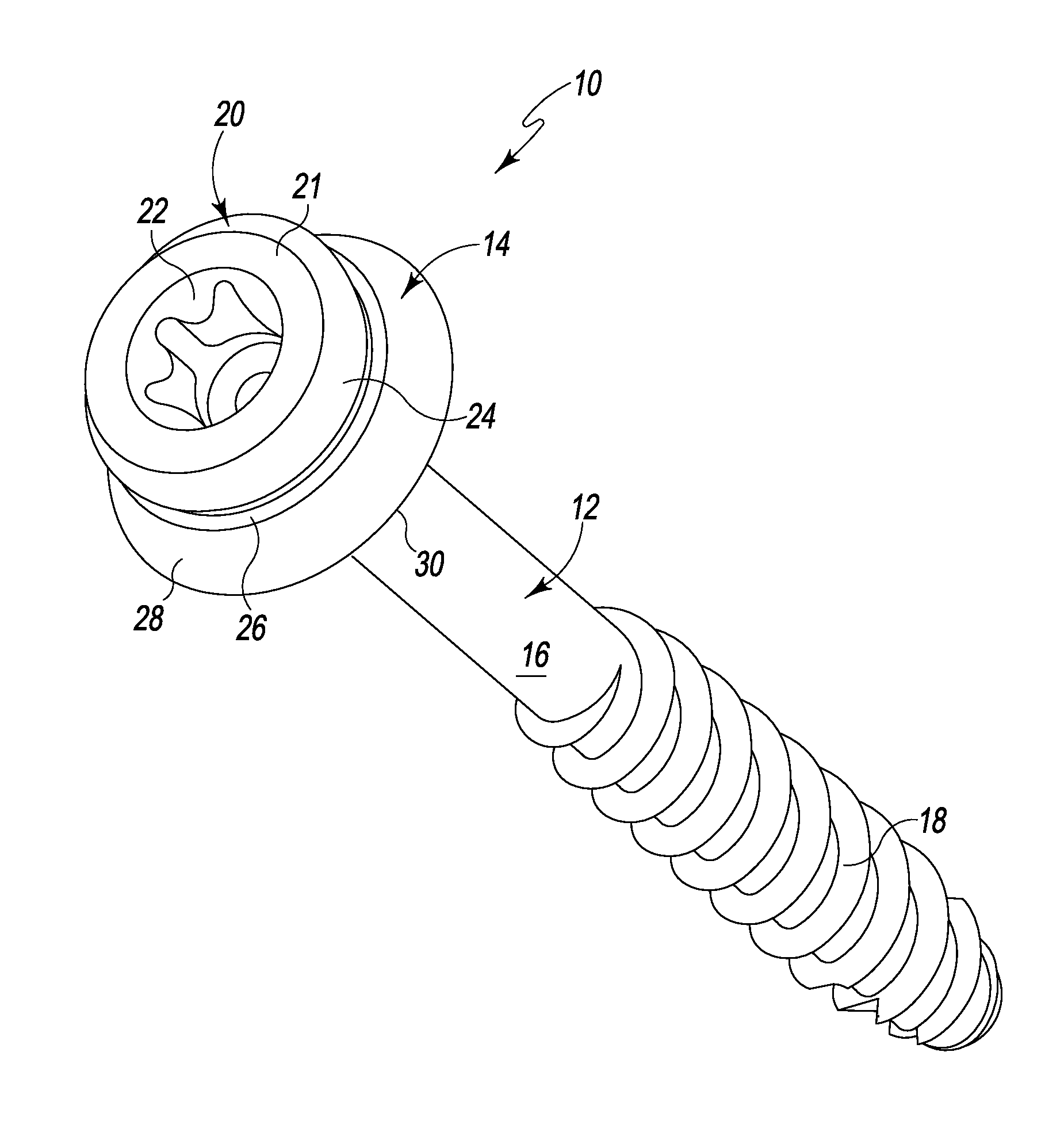
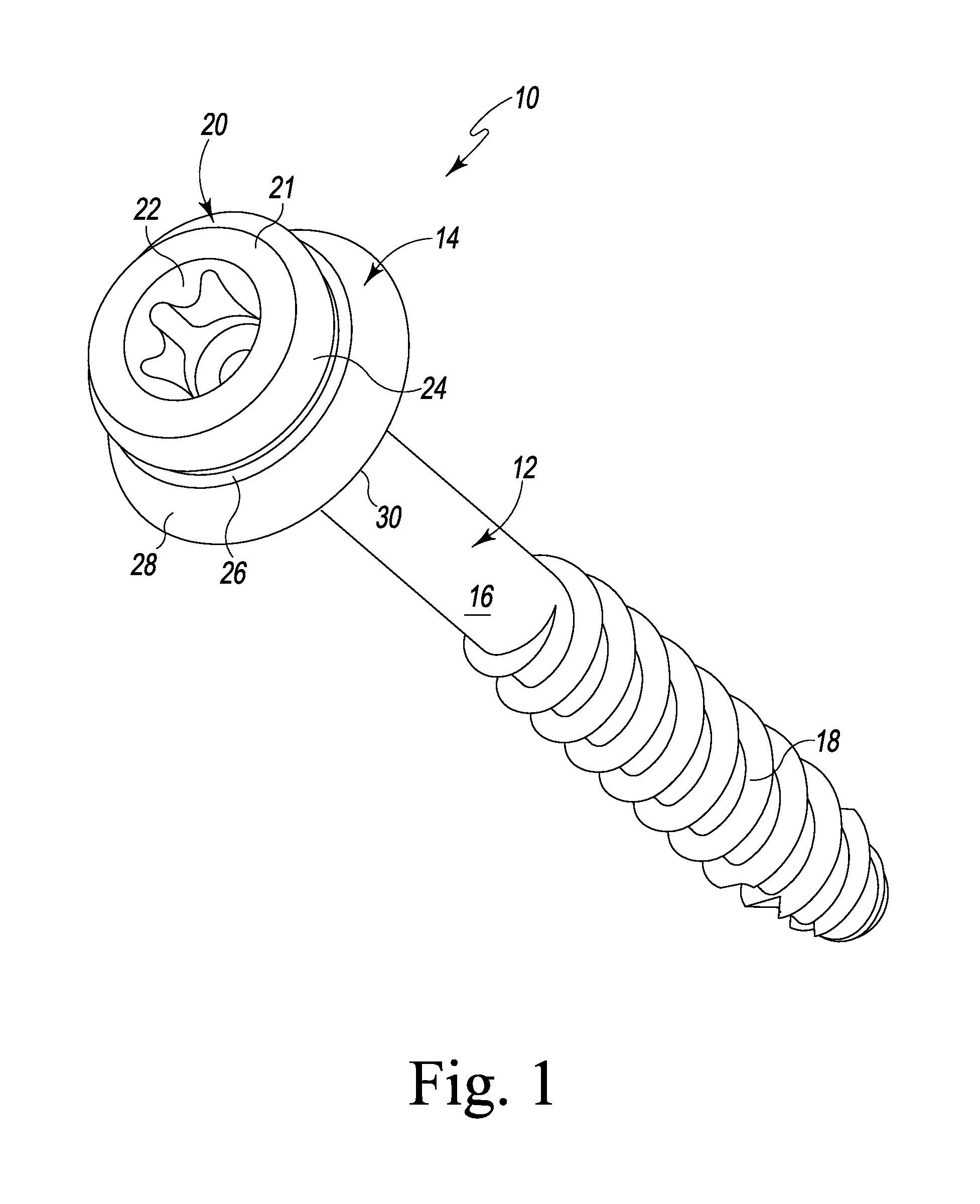
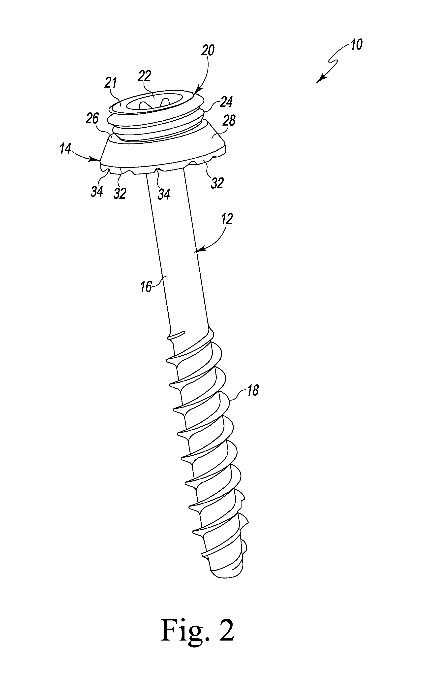
[0032]Referring to FIGS. 1-3 there is shown various views of an embodiment of a spinal facet fixation system generally designated 10 fashioned in accordance with the principles of the present invention. The spinal facet fixation system may alternatively be named a spinal facet screw system but will hereinafter be termed a spinal facet fixation system 10. The spinal facet fixation system 10 has a facet screw component (facet screw) 12 and a washer component (washer) 14. The components 12 and 14 are fabricated from a biocompatible material such as titanium, stainless steel or otherwise.

[0033]As particularly shown in FIG. 4, the facet screw 12 is formed by a head 20 with an elongated shaft 16 extending from an underside or undersurface 19 of the head 20. The shaft 16 has threads 18 on an outside surface thereof (external threads 18) that extend from an end or tip of the shaft 16 to about halfway up toward the head 20. The shaft 16 may have other thread variations. Additionally, the ext...


PUM


Abstract

A spinal facet bone screw system provides tactile feedback to the user during installation to aid in determining when one or more components of the spinal facet bone screw system have been installed or implanted. The spinal facet bone screw system has a spinal facet screw and a washer. Tactile installation feedback is provided at an interface between a friction surface of the head of the spinal facet screw and a friction surface of the pocket of the washer to determine when the spinal facet screw has reached its full insertion depth. The bottom or undersurface of the washer that abuts a spinal facet bone or other spinal component during installation may be configured and/or textured to further provide tactile installation feedback as between the washer and the bone or other spinal component.

Description

RELATED APPLICATIONS[0001]This patent application claims the benefit of and / or priority under 35 U.S.C. §119(e) to U.S. Provisional Patent Application Ser. No, 61 / 355,905 filed Jun. 17, 2010, entitled “Spinal Facet Fixation System” the entire contents of which is specifically incorporated herein by this reference.BACKGROUND OF THE INVENTION[0002]1. Field of the Invention[0003]The present invention relates to devices for the spine and, more particularly, to devices for restricting, limiting and / or stopping motion between adjacent vertebrae.[0004]2. Background Information[0005]As we age various changes can occur in the body especially with respect to the spinal column or spine. For instance, the ligaments of the spine can thicken and calcify (i.e. harden from deposits of calcium), bone and joints may enlarge, bone spurs called osteophytes may form, spinal discs may break down, collapse, bulge and / or herniate. Moreover, one vertebra may slip over another vertebra (spondylolisthesis). F...

Claims


Application Information

Patent Timeline
IPC IPC(8): A61B17/88A61B17/86
CPCA61B17/7064A61B17/8605A61B2017/00858A61B17/8695A61B17/864
Inventor BUTLER, MICHAEL S.PREDICK, DANIEL
Owner LIFE SPINE INC
Why Eureka
Try Eureka