
Method and apparatus for conversion of heat to electrical energy using polarizable materials and an internally generated poling field

a technology of polarizable materials and internal generation, applied in electrical apparatus, thermoelectric devices with dielectric constant thermal change, thermoelectric devices, etc., can solve problems such as impede the use of spontaneous polarization as a way of generating electrical energy, and achieve the effect of greater output of electrical energy

Inactive Publication Date: 2011-12-29
THE NEOTHERMAL ENERGY
View PDF4 Cites 12 Cited by
  • Summary
  • Abstract
  • Description
  • Claims
  • Application Information

AI Technical Summary

Benefits of technology

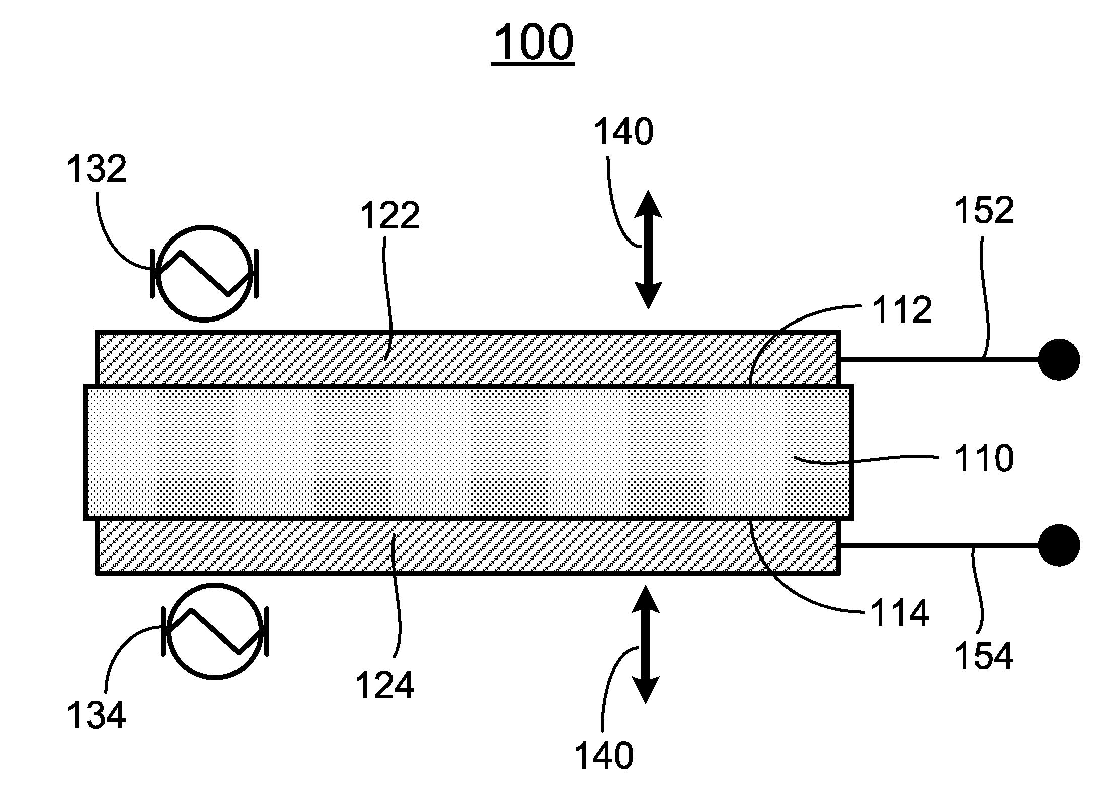
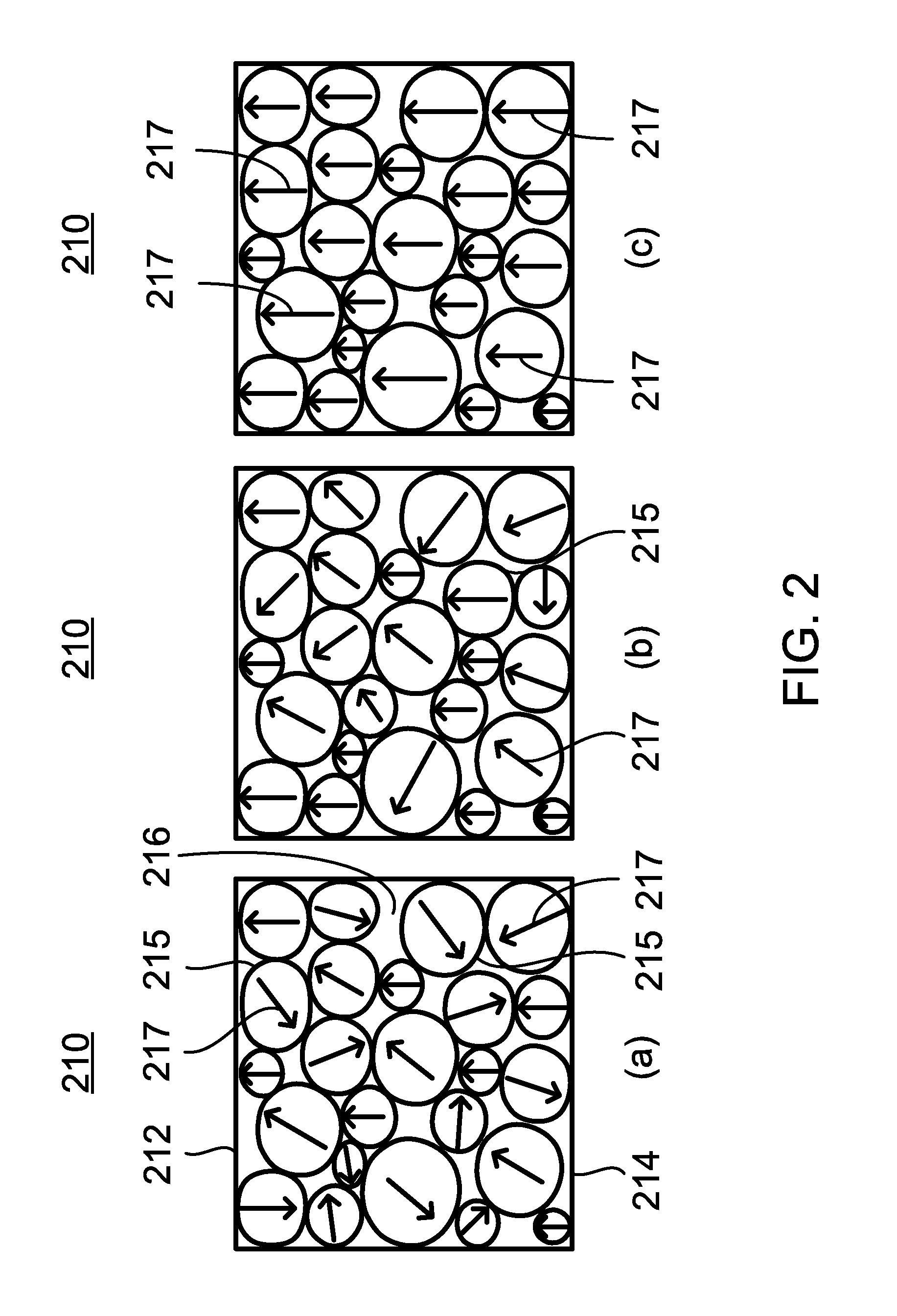
[0011]When in the ferroelectric phase, very strongly polarized electric dipoles develop spontaneously in the unit cells of one or more ferroelectrics, which occurs without the application of an external field. By poling to align the unit cells and domains, the polarization of the individual unit cells and domains combines to produce an extremely large net spontaneous polarization in the overall material system. That net polarization is designated as Ps. The present invention utilizes the spontaneous polarization, together with the rapid change in that polarization that occurs during thermal cycling, to convert heat to electrical energy. The present invention does not require temperature variability of the dielectric constant. The electrical energy that is generated as a result of spontaneous polarization, and released with the diminution or disappearance of polarization, can be much greater than the electrical energy generated using a ferroelectric through the application of an external electric field in the variable capacitor mode.
[0015]As disclosed in U.S. patent application Ser. No. 12 / 465,924 and U.S. Pat. No. 7,982,360 to Erbil, by utilization of one or more heat exchangers the temperature of a ferroelectric material can be cycled around the phase transition temperature, or Curie temperature, Tc, so that thermal energy can be effectively converted to electrical energy with the invention operating between a heat source and heat sink. Electric energy is generated by cycling the ferroelectric module above and below the phase transition temperature in accordance with the apparatus and method described in that application. Various thermodynamic cycles can be used to exploit spontaneous polarization in ferroelectrics for the purpose of converting heat to electricity. The general cycle set forth in U.S. patent application Ser. No. 12 / 465,924 and U.S. Pat. No. 7,982,360 can be used with the present invention in order to generally eliminate the need for applying an external voltage to pole the ferroelectric during each cycle.
[0016]A specific thermodynamic cycle that has four steps, two of which are isothermal and two of which occur at constant polarization, is disclosed in U.S. patent application Ser. No. 13 / 226,799. The present invention can be used in conjunction with that or other thermodynamic cycles, thereby eliminating the need for application of external poling voltage. Using that cycle or another cycle with the present invention, total polarization is not allowed to drop below a value PL at any point of the cycle. PL is the minimum level at which the resulting field is sufficient to cause poling when the ferroelectric is transitioned into its ferroelectric phase.
[0018]In the next step of the cycle, the circuit is opened while the ferroelectric or other polarizable material is heated to a relatively high temperature, TH, above the transition temperature. Total polarization remain constant during that step, and the material goes into a metastable state. During the final step of the cycle, the circuit is again closed and heat is input isothermally until polarization is reduced to PL. During that step, the screened charges on the electrode become unscreened and are discharged into external circuitry at a self-generated high voltage. However, all of the charges on the electrode are not removed. Instead, the circuit is opened at a point where a great enough residual charge remains to establish a field sufficient for poling, which corresponds to PL. Poling from such a residual field rather than by applying an external voltage can enhance the overall output of electrical energy during the course of a cycle.
[0019]The cycle is then repeated continuously, with the result that thermal energy is continuously converted to electrical energy at high voltage. The invention can be used with ferroelectrics that are in either solid or liquid form, the latter including liquid ferroelectrics and ferroelectric fine crystals suspended in liquid. For example, the solid materials that can be used include ceramic ferroelectrics, ferroelectric polymers, and other polarizable polymers. In addition to the ordinary ferroelectrics, extrinsic (or improper) ferroelectrics, such as boracites and sodalites, can be used with this invention. With intrinsic ferroelectrics, polarization represents a second order parameter, which is coupled to some primary order parameter. Exploiting the spontaneous polarization of ferroelectrics with the present invention allows a robust conversion of heat to electrical energy over a wide range of temperatures using heat supplied from a many sources, both naturally occurring and generated. Heat can be input to the ferroelectric from the heat source or withdrawn from the ferroelectric to the heat sink by conduction, convection or radiation or by any combination thereof, and by one or two-phase heat transfer systems.

Problems solved by technology

Although application of large electric fields are essential for operation of variable capacitor devices and the Olsen cycle, the application of such external fields, and fields beyond the minimum required for poling, generally impede the use of spontaneous polarization as a way of generating electrical energy.

Method used


Image

  • Method and apparatus for conversion of heat to electrical energy using polarizable materials and an internally generated poling field
  • Method and apparatus for conversion of heat to electrical energy using polarizable materials and an internally generated poling field
  • Method and apparatus for conversion of heat to electrical energy using polarizable materials and an internally generated poling field

Examples


Embodiment Construction

[0067]The present invention is more particularly described in the following examples that are intended as illustrative only since numerous modifications and variations therein will be apparent to those skilled in the art. Various embodiments of the invention are now described in detail. Referring to the drawings, like numbers indicate like components throughout the views. As used in the description herein and throughout the claims that follow, the meaning of “a”, “an”, and “the” includes plural reference unless the context clearly dictates otherwise. Also, as used in the description herein and throughout the claims that follow, the meaning of “in” includes “in” and “on” unless the context clearly dictates otherwise. Additionally, some terms used in this specification are more specifically defined below.

[0068]The terms used in this specification generally have their ordinary meanings in the art, within the context of the invention, and in the specific context where each term is used....


PUM


Abstract

A method for converting heat to electricity by exploiting changes in spontaneous polarization that occur in electrically polarizable materials is described. The method uses an internally generated field to achieve poling during cycling. The internal poling field is produced by retaining residual free charges on the electrodes at the appropriate point of each cycle. The method obviates the need for applying a DC voltage during cycling and permits the use of the electrical energy that occurs during poling rather than an external poling voltage which detracts from the net energy produced per cycle. The method is not limited to a specific thermodynamic cycle and can be used with any thermodynamic cycle for converting heat to electricity by thermally cycling electrically polarizable materials. The electrical energy generated can be used in various applications or stored for later use. An apparatus for converting heat to electricity is also described.

Description

CROSS-REFERENCE TO RELATED PATENT APPLICATION[0001]This application is a continuation-in-part of U.S. patent application Ser. No. 12 / 465,924, filed May 14, 2009, now allowed. This application also claims the benefit of Provisional U.S. Patent Application Ser. No. 61 / 387,760, filed Sep. 29, 2010, pending. Each of the above applications is incorporated by reference herein in its entirety.[0002]Some references, which may include patents, patent applications and various publications, are cited and discussed in the description of this invention. The citation and / or discussion of such references is provided merely to clarify the description of the present invention and is not an admission that any such reference is “prior art” to the invention described herein. All references cited and discussed in this specification are incorporated herein by reference in their entireties and to the same extent as if each reference were individually incorporated by reference.FIELD OF THE INVENTION[0003]T...

Claims


Application Information

Patent Timeline
IPC IPC(8): H01L35/02H01L35/28
CPCH01L37/02H10N15/10
Inventor ERBIL, AHMETWALBERT, DAVID F.
Owner THE NEOTHERMAL ENERGY
Learn More