Driving method of liquid crystal display device and liquid crystal display device

a technology of liquid crystal display device and driving method, which is applied in the direction of static indicating device, instruments, etc., can solve the problems of high power consumption of backlight, low production cost of stn type liquid crystal display device, and inability to display moving images. achieve the effect of improving light utilization efficiency

Inactive Publication Date: 2013-10-22
FUJITSU LTD
View PDF40 Cites 2 Cited by
  • Summary
  • Abstract
  • Description
  • Claims
  • Application Information

AI Technical Summary

Benefits of technology

[0012]An object of the present invention is to provide a driving method of a liquid crystal display device and a liquid crystal display device, capable of improving the light utilization efficiency.

Problems solved by technology

Since the reflection type liquid crystal display devices have poor visibility resulting from the reflected light amount that varies depending on environmental conditions, the transmission type liquid crystal display devices are generally used as display devices of, particularly, personal computers displaying a multi-color or full-color image.
The STN type liquid crystal display devices have comparatively low production costs, but they are not suitable for the display of a moving image because they are susceptible to crosstalk and comparatively slow in the response rate.
For this reason, in the TFT-TN type liquid crystal display devices, a lot of power is consumed by the back-light, and there would be a problem when used with a portable battery power source.
Moreover, the TFT-TN type liquid crystal display devices have other problems including a low response rate, particularly, in displaying half tones, a narrow viewing angle, and a difficult color balance adjustment.
Therefore, the time contributing to actual display is a half of the total time, and there is a problem that the light utilization efficiency given by the ratio of the screen brightness to the light source brightness is low (the screen brightness / back-light brightness percentage is 6% in the conventional example adopting the drive sequence shown in FIG. 2).
Furthermore, since the ferroelectric liquid crystal has spontaneous polarization, it is necessary to store charges twice more than the spontaneous polarization in each pixel electrode for selective scanning of each pixel electrode, and thus there is a problem that a liquid crystal material having large spontaneous polarization can not be used in view of the facts that the capacity of each pixel electrode and the drive voltage are not so high.
Besides, when the incorporation of the liquid crystal display device into a portable apparatus is taken into consideration, it is preferred to drive the liquid crystal display device by a low voltage, but there is a problem that driving by a sufficiently low voltage has not yet been realized (the drive voltage is 12 V in the conventional example using a ferroelectric liquid crystal having spontaneous polarization of 11 nC / cm2).

Method used


Image

  • Driving method of liquid crystal display device and liquid crystal display device
  • Driving method of liquid crystal display device and liquid crystal display device
  • Driving method of liquid crystal display device and liquid crystal display device

Examples


first embodiment

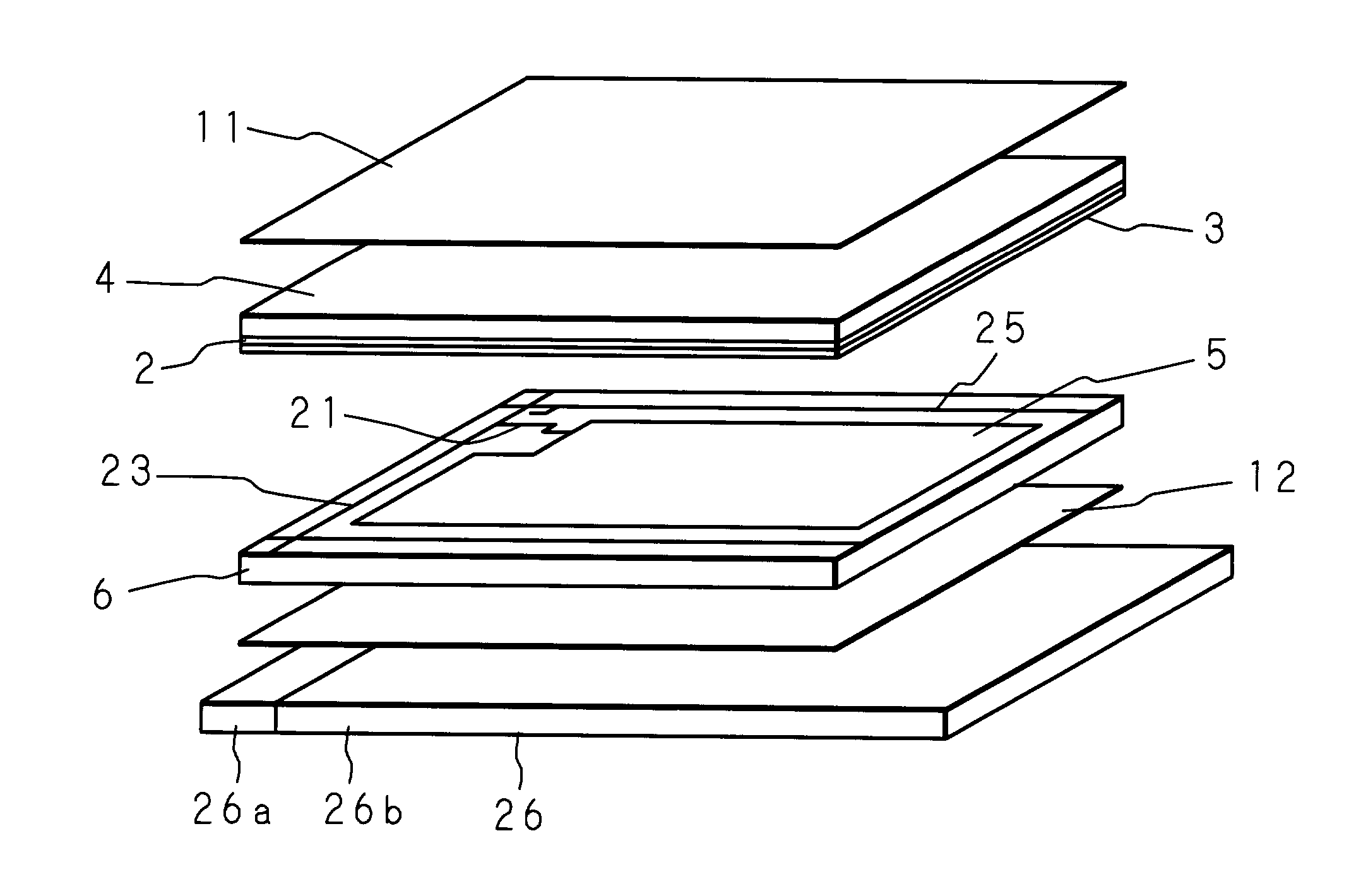
[0056]First, the liquid crystal panel 1 shown in FIGS. 4 and 5 was fabricated as follows. After washing a TFT substrate having the pixel electrodes 5 (800×600 pixels with a diagonal length of 12.1 inches) and a common electrode substrate having the common electrode 2 and the RGB color filter / black matrix 3, they were coated with polyimide and then baked for one hour at 200° C. to form the alignment films 7 and 8 made of about 200 Å thick polyimide films.

[0057]Further, these alignment films 7 and 8 were rubbed with a cloth made of rayon, and stacked with a gap being maintained therebetween by the spacers 10 made of silica having an average particle size of 1.6 μm so as to fabricate an empty panel. A ferroelectric liquid crystal material composed mainly of naphthalene-based liquid crystals (for example, a material disclosed by A. Mochizuki, et. al.: Ferroelectrics, 133,353 (1991)) was sealed in this empty panel to form the liquid crystal layer 9. The magnitude of spontaneous polarizat...

second embodiment

[0062]A liquid crystal display device was constructed by stacking the liquid crystal panel 1 fabricated under the same conditions as in the first embodiment and the back-light 26 formed of LEDs of easy switching.

[0063]In addition, according to the drive sequences shown in FIGS. 7 and 8, the TFTs 21 of the respective pixel electrodes 5 were driven on a line by line basis to apply a voltage corresponding to the image data. The selection period of each line was made 7 μs. The data-erasing scanning was performed twice.

[0064]The maximum applied voltage to the liquid crystal corresponding to the image data was made (Vcom+7) V, the first applied voltage to the liquid crystal by batch selection of all the pixel electrodes (batch selection of all the lines) during erasure was made (Vcom−8) V, and the second applied voltage was made equal to Vcom. Moreover, a time interval of 500 μs in which the liquid crystal can respond sufficiently was set between the first voltage application and the seco...

third embodiment

[0067]Like the first embodiment, after washing a TFT substrate having the pixel electrodes 5 (800×600 pixels with a diagonal length of 12.1 inches) and a common electrode substrate having the common electrode 2 and the RGB color filter / black matrix 3, they were coated with polyimide and then baked for one hour at 200° C. to form the alignment films 7 and 8 made of about 200 Å thick polyimide films.

[0068]Further, these alignment films 7 and 8 were rubbed with a cloth made of rayon, and stacked with a gap being maintained therebetween by the spacers 10 made of silica having an average particle size of 1.6 μm so as to fabricate an empty panel. A ferroelectric liquid crystal material composed mainly of naphthalene-based liquid crystals (for example, a material disclosed by A. Mochizuki, et. al.: Ferroelectrics, 133,353 (1991)) was sealed in this empty panel to form the liquid crystal layer 9. The magnitude of spontaneous polarization of the sealed ferroelectric liquid crystal material w...


PUM


Abstract

In a liquid crystal display device that uses a liquid crystal material having spontaneous polarization and is actively driven by a TFT, a voltage corresponding to image data is applied twice by driving the TFT of each pixel electrode on a line by line basis of a liquid crystal panel, during writing in one frame. During erasure in one frame, voltage application to liquid crystal by batch selection of all the pixel electrodes is performed three times. With this three times of voltage application, it is possible to achieve a black display state in each pixel and make the stored charge amount at the liquid crystal in each pixel substantially zero.

Description

[0001]This is a continuation-in-part of U.S. patent application Ser. No. 09 / 946,265, filed Sep. 5, 2001, now U.S. Pat. No. 7,081,873 issued Jul. 25, 2006.BACKGROUND OF THE INVENTION[0002]The present invention relates to a driving method of a liquid crystal display device using a liquid crystal material having spontaneous polarization and also relates to a liquid crystal display device adopting the driving method.[0003]Along with the recent development of so-called information-oriented society, electronic apparatuses, such as personal computers and PDA (Personal Digital Assistants), have been widely used. Further, with the spread of such electronic apparatuses, portable apparatuses that can be used in offices as well as outdoors have been used, and there are demands for small-size and light-weight of these apparatuses. Liquid crystal display devices have been widely used as one of the means to satisfy such demands. Liquid crystal display devices not only achieve small size and light ...

Claims


Application Information

Patent Timeline
Patent Type & Authority Patents(United States)
IPC IPC(8): G09G3/36G09G3/34
CPCG09G3/3406G09G3/3651G09G2310/0235G09G2310/0237G09G2310/0283G09G2310/063G09G2310/08
Inventor YOSHIHARA, TOSHIAKITADAKI, SHINJIMAKINO, TETSUYASHIROTO, HIRONORIKIYOTA, YOSHINORIBETSUI, KEIICHI
Owner FUJITSU LTD
Why Eureka
Try Eureka