Vehicle driving apparatus

a technology of driving apparatus and electric motor, which is applied in the direction of electric propulsion mounting, electric motor propulsion transmission, locomotives, etc., can solve the problems of substantially low heat release capacity achieve high cooling efficiency, eliminate dimensional constraints, and maintain constant high cooling efficiency of totally enclosed electric motor

Active Publication Date: 2011-12-29
MITSUBISHI ELECTRIC CORP
View PDF10 Cites 1 Cited by
  • Summary
  • Abstract
  • Description
  • Claims
  • Application Information

AI Technical Summary

Benefits of technology

[0011]According to an aspect of the present invention, a ventilating duct is disposed to connect a suction inlet of a totally enclosed electric motor to an opening formed on a side cover. Therefore, it becomes possible to supply the outside air from the outside of the vehicle as cooling wind to the totally enclosed electric motor. This eliminates the possibility of a conventional problem in which high temperature air affected by the exhaust heat around the totally enclosed electric motor is supplied. As a result, the cooling efficiency of the totally enclosed electric motor can be constantly maintained at a high level.
[0012]According to another aspect of the present invention, the cooling wind from the outside of the vehicle is supplied via the ventilating duct with the use of an air suction feature of an outside air ventilating flue that is disposed in the totally enclosed electric motor. This eliminates the need of newly disposing a device for producing a forced draft. Moreover, unlike in the conventional technology, the vehicle running wind generated when the vehicle is running is not used. Thus, even if it is not possible to obtain sufficient vehicle running wind when the vehicle slows down or when the electric motor is operating after the vehicle comes to a halt, it is still possible to maintain a high cooling efficiency.
[0013]According to still another aspect of the present invention, the totally enclosed electric motor is disposed outside the frame of a chassis. This eliminates the dimensional constraints regulated by the chassis while installing the totally enclosed electric motor. Thus, it becomes possible to dispose a high-capacity the totally enclosed electric motor. That is, by loading the totally enclosed electric motor to the vehicle body portion other than the chassis, it becomes possible to secure sufficient space and thus increase the capacity of the totally enclosed electric motor.
[0014]Moreover, since the totally enclosed electric motor is disposed outside the frame of the chassis, a shaft is disposed to connect the totally enclosed electric motor to an axle. In addition to its primary function of transmitting the rotary drive force of the totally enclosed electric motor to the axle, the shaft has good heat conductivity because of its metallic material. Thus, by helping the heat to release from the totally enclosed electric motor, the shaft contributes to the cooling effect. This enables achieving further enhancement in the cooling efficiency of the totally enclosed electric motor.
[0015]In this way, according to an aspect of the present invention, in addition to achieving the conventional advantages, such as less maintenance and low vehicular noise, of a totally enclosed electric motor; it is possible to provide a vehicle driving apparatus that includes a totally enclosed electric motor that has a high capacity as well as enhanced cooling efficiency.

Problems solved by technology

Meanwhile, with the aim of enhancing comfort, there is a demand for noise reduction in the vehicular environment; and noise reduction of electric motors is an issue of particular concern among the issues regarding open type electric motors.
Because of its structure, the heat releasing capacity of a totally enclosed electric motor is substantially low as compared to an open type electric motor.

Method used


Image

  • Vehicle driving apparatus
  • Vehicle driving apparatus
  • Vehicle driving apparatus

Examples


first embodiment

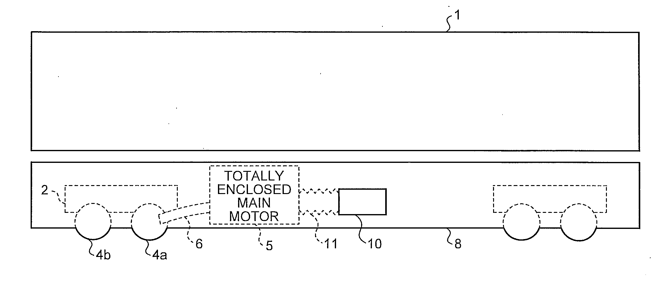
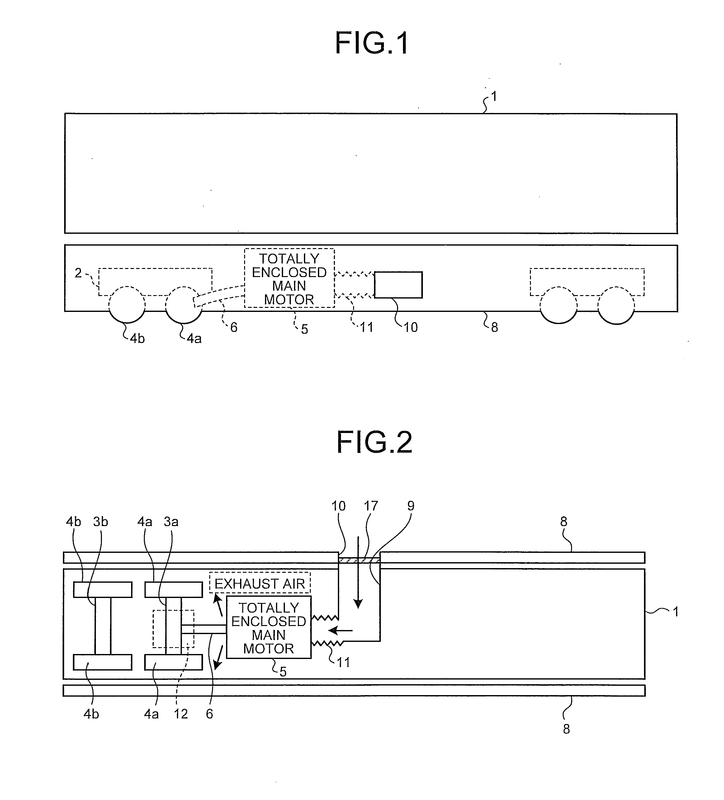
[0057]FIG. 1 is a schematic side view illustrating a configuration of a vehicle driving apparatus according to the present embodiment. FIG. 2 is a schematic plan view illustrating the configuration of the vehicle driving apparatus according to the present embodiment when the bottom part of the corresponding vehicle is viewed from below. The vehicle driving apparatus according to the present embodiment is disposed in a train vehicle or the like, and runs the corresponding vehicle by converting electric power into torque with the use of an electric motor of a totally enclosed type electric motor (hereinafter referred to as a totally enclosed electric motor).

[0058]In the bottom part of a vehicle body 1, which is the main part of the train vehicle, are disposed chassis 2. On each chassis 2 are disposed axles 3a and 3b. A wheel 4a is impactedly fixed to each end of the axle 3a, while a wheel 4b is impactedly fixed to each end of the axle 3b. In the example illustrated in FIG. 1, two chas...

second embodiment

[0083]FIG. 5 is a schematic plan view illustrating a configuration of the vehicle driving apparatus according to the present embodiment when the bottom part of the corresponding vehicle is viewed from below. In the present embodiment, the structure of a ventilating duct 19 is different from the structure of the ventilating duct 9 in the first embodiment. Meanwhile, in FIG. 5, the constituent elements identical to those illustrated in FIG. 2 are referred to by the same reference numerals and the detailed description thereof is omitted.

[0084]As illustrated in FIG. 5, the ventilating duct 19 is a T-shaped duct having three open ends. One of the three open ends is connected to the suction inlet 58 of the totally enclosed main motor 5. One of the remaining two open ends is connected to an opening 18a that is formed on the side covers 8 disposed at one side of the vehicle, while the other of the remaining two open ends is connected to an opening 18b that is formed on the side covers 8 dis...

third embodiment

[0086]FIG. 7 is a schematic plan view illustrating a configuration of the vehicle driving apparatus according to the present embodiment when the bottom part of the corresponding vehicle is viewed from below. FIG. 6 is a schematic plan view illustrating an exemplary modification of the configuration of the vehicle driving apparatus according to the present embodiment when the bottom part of the corresponding vehicle is viewed from below. Meanwhile, in FIGS. 6 and 7, the constituent elements identical to those illustrated in FIG. 2 are referred to by the same reference numerals and the detailed description thereof is omitted.

[0087]As illustrated in FIG. 7, in the present embodiment, a ventilating duct 30 for exhaust air is disposed in the configuration according to the second embodiment illustrated in FIG. 5. More particularly, one end of the ventilating duct 30 is connected to the exhaust outlet 59 of the totally enclosed main motor 5 and the other end of the ventilating duct 30 is c...


PUM


Abstract

In a vehicle in which side covers are disposed at the underfloor sides of a vehicle body, a totally enclosed main motor is disposed outside a frame of a chassis. The totally enclosed main motor includes an outside air ventilating flue through which the outside air is suctioned from a suction inlet, circulated and then exhausted from an exhaust outlet. The totally enclosed main motor uses the outside air ventilating flue to release heat generated internally to the outside. One end of a ventilating duct is connected to the suction inlet and the other end opens toward the outside of the vehicle at the side covers. With this, it is possible to supply the outside air from the outside of the vehicle thereby enhancing the cooling efficiency. Moreover, it is possible to use the totally enclosed main motor of a high capacity by disposing outside the frame of the chassis.

Description

TECHNICAL FIELD[0001]The present invention relates to a vehicle driving apparatus that drives a vehicle of an electric train or the like, and particularly relates to a vehicle driving apparatus that uses a totally enclosed electric motor.BACKGROUND ART[0002]A vehicle driving apparatus for driving a vehicle of an electric train or the like uses, as a driving source, an electric motor that is disposed under the floor of the vehicle body and runs the vehicle by transferring the torque of the electric motor to the wheels of the vehicle via gear devices and axles disposed on a chassis. With the increase in the running speed of vehicles, there is a demand for further reduction in the size and weight as well as further increase in the capacity of electric motors.[0003]Conventionally, as an electric motor of this kind, an open type electric motor is disposed in which outside air is drawn in and used as cooling wind. Since outside air containing dust is drawn in an open type electric motor, ...

Claims


Application Information

Patent Timeline
Patent Type & Authority Applications(United States)
IPC IPC(8): B60K1/00
CPCB61C5/02B61C17/04B61C9/52
Inventor SAKANE, MASAMICHI
Owner MITSUBISHI ELECTRIC CORP
Why Eureka
Try Eureka