
Treatment of solutions or wastewater

Inactive Publication Date: 2011-12-29
THE UNIV OF QUEENSLAND
View PDF0 Cites 35 Cited by
  • Summary
  • Abstract
  • Description
  • Claims
  • Application Information

AI Technical Summary

Benefits of technology

[0009]It is an object of some embodiments of the present invention to provide a method for treating a wastewater stream to produce a wastewater stream having reduced organic content and other desirable characteristics such as decreased salt content or reduced tendency for ions dissolved in the solution to precipitate.
[0013]a) reduce the pH of the stream passed to the anode to minimise or suppress precipitation of dissolved cations; or
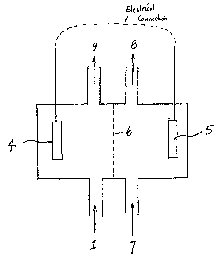
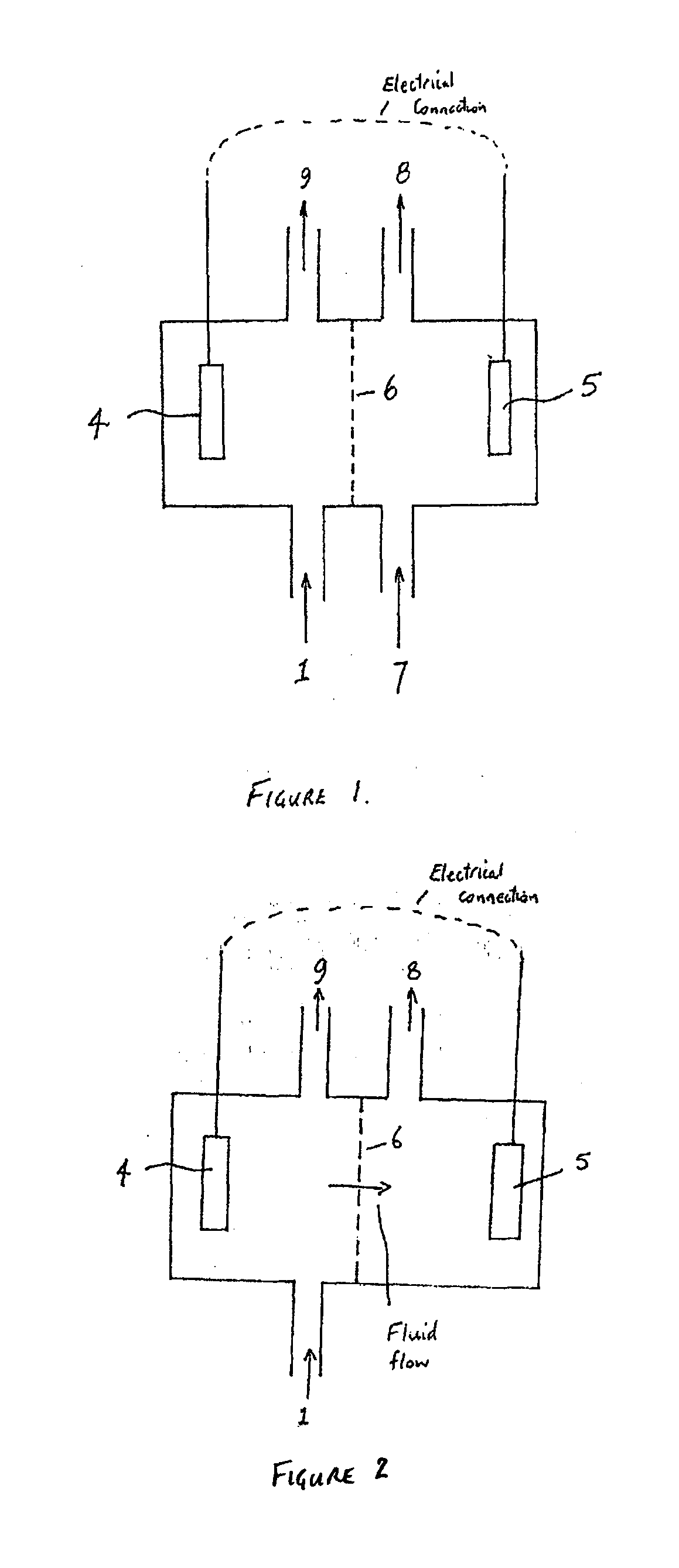
[0017]In one embodiment of the present invention the bioelectrochemical system comprises an anode chamber and a cathode chamber separated by an ion permeable membrane, as known to the person skilled in the art. Ion permeable membranes suitable for use in the present invention include any ion permeable membranes that may be used in bioelectrochemical systems (Kim et al., Environ. Sci. Technol., 2007, 41, 1004-1009; Rozendal et al., Water Sci. Technol., 2008, 57, 1757-1762). Such ion permeable membranes may include ion exchange membranes, such as cation exchange membranes and anion exchange membranes. Porous membranes, such as microfiltration membranes, ultrafiltration membranes, and nanofiltration membranes, may also be used in the bioelectrochemical system used in the present invention. The ion permeable membrane facilitates the transport of positively and / or negatively charged ions through the membrane, which compensates for the flow of the negatively charged electrons from anode to cathode and thus maintains electroneutrality in the system. Pervaporation membranes and membranes as used for membrane distillation may also be used.
[0061]a) reduce the pH of the stream passed to the anode to minimise or suppress precipitation of dissolved cations; or

Problems solved by technology

The anode reaction in bioelectrochemical systems produces protons or consumes hydroxyl ions which can acidify the biofilm surrounding the anode and negatively affect the performance of the bioelectrochemical system.
The systems generally suffer from fuel crossover from anode to cathode.

Method used


Image

  • Treatment of solutions or wastewater
  • Treatment of solutions or wastewater
  • Treatment of solutions or wastewater

Examples


Embodiment Construction

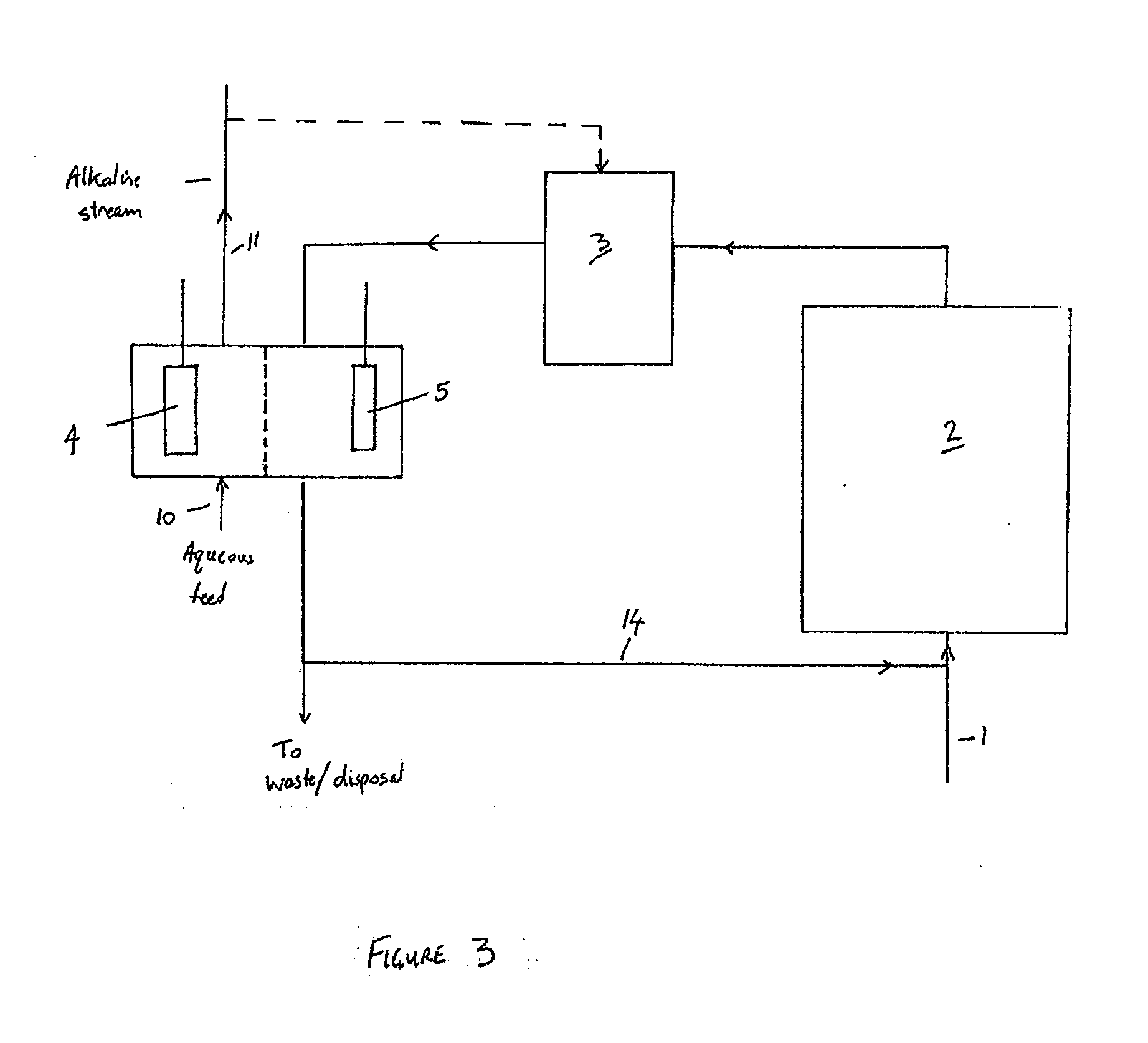
[0095]Microbial fuel cells (MFCs) have generated considerable interest in the past few years. In a nutshell, MFCs use whole microorganisms as biocatalysts for the oxidation of (in)organic electron donors at an anode. From the anode, electrons gained from the oxidation are conveyed towards a cathode, the latter has a higher potential. As electrons flow from a low to a high potential, a power output is generated. MFCs are nowadays generally referred to as Bioelectrochemical Systems (BESs). One particularly complex issue BESs face is caused by the presence of cations, such as sodium and potassium, in wastewater or other feedstock supplied to the anode. As the concentration of these cations is generally much higher than the proton concentration, they are typically transported to a high extent through the cation exchange membrane of the BES to restore the charge balance between anode and cathode. As a result, the anode tends to acidify due to proton generation in the anode reaction, whil...


PUM

PropertyMeasurementUnit
Concentrationaaaaaaaaaa

Abstract

A method for treating a wastewater stream containing organic material or inorganic material comprising passing the wastewater stream to an anode or a cathode of a bioelectrochemical system to thereby alter the pH of the wastewater stream to: a) reduce the pH of the stream passed to the anode to minimise or suppress precipitation of dissolved cations; or b) increase the pH of the stream passed to the cathode to produce an alkaline stream; or c) reduce the pH of the stream passed to the anode to produce an acid containing stream. In one embodiment, a caustic soda solution is produced at the cathode and recovered for storage and subsequent use.

Description

FIELD OF THE INVENTION[0001]In one aspect, the present invention relates to a method for treating a wastewater stream. In another aspect, the present invention relates to a method for forming an acidic solution or an alkaline solution.BACKGROUND TO THE INVENTION[0002]Many industries require substantial amounts of caustic soda and / or hydrochloric acid for their operations. Caustic soda is typically made via the chloralkali process, in which a NaCl brine is electrolysed. There are 3 main methods used in this regard, being the Mercury cell process (also called the Castner-Kellner process), the Diaphragm cell process and the Membrane cell process. The latter uses a Nafion cation exchange membrane to separate the cathode and anode reactions. Only sodium ions and some water pass through the used membrane.[0003]Hydrochloric acid is produced industrially via two methods. First, during the chloralkali process it is formed at the anode, where chloride is converted to chlorine, which is recomb...

Claims


Application Information

Patent Timeline
IPC IPC(8): C02F9/14C02F1/44C02F3/28C25B15/00C02F1/66C02F1/46C02F101/10C02F101/30C02F103/08C02F103/28C02F103/32
CPCC02F1/4618Y02E60/527C02F3/005C02F3/286C02F9/00C02F2001/46133C02F2201/46115C02F2201/46125C02F2201/46165C02F2201/4618C02F2209/06C02F1/66H01M8/16C02F3/28C02F1/46Y02E60/50Y02W10/37
Inventor RABAEY, KORNEEL P.H.L.A.ROZENDAL, RENE A.
Owner THE UNIV OF QUEENSLAND
Learn More