Brake Control System For Dual Mode Vehicle

a technology of brake control system and dual-mode vehicle, which is applied in the direction of braking system, braking components, transportation and packaging, etc., can solve the problems of loss of vehicle control by the operator, unfavorable operation, and unfavorable operation

Active Publication Date: 2011-12-29
DEERE & CO
View PDF15 Cites 29 Cited by
  • Summary
  • Abstract
  • Description
  • Claims
  • Application Information

AI Technical Summary

Benefits of technology

[0003]Accordingly, an object of this invention is to provide a steering control system wh

Problems solved by technology

First, when in operating in autonomous mode, a single CPU must be able engage the brakes in the event of a single point failure.
Otherwise, inability to bring the vehicle to a halt with the E-H braking system during unmanned operation may lead to an unsafe condition.
Seco

Method used


Image

  • Brake Control System For Dual Mode Vehicle
  • Brake Control System For Dual Mode Vehicle

Examples


Embodiment Construction

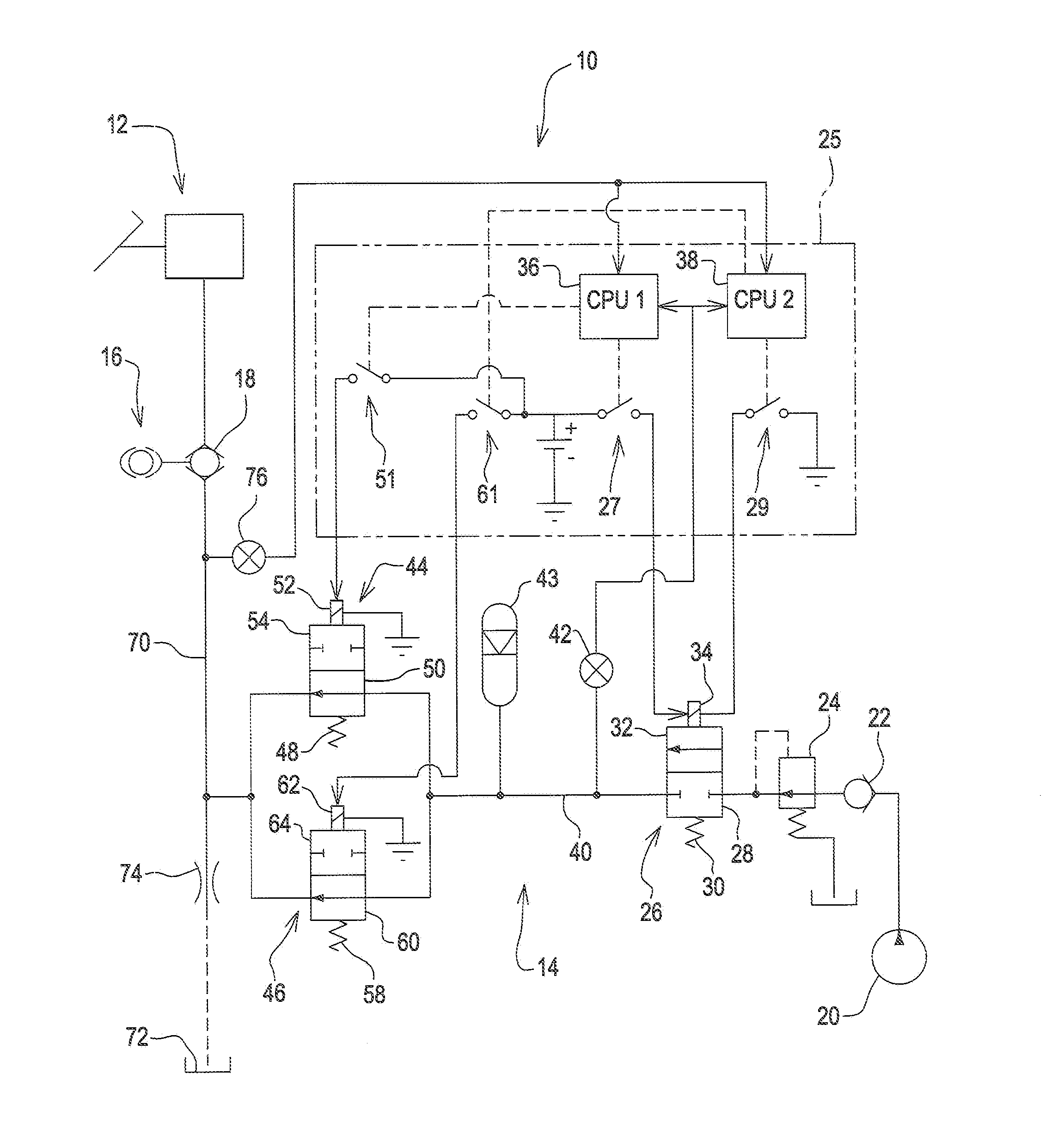
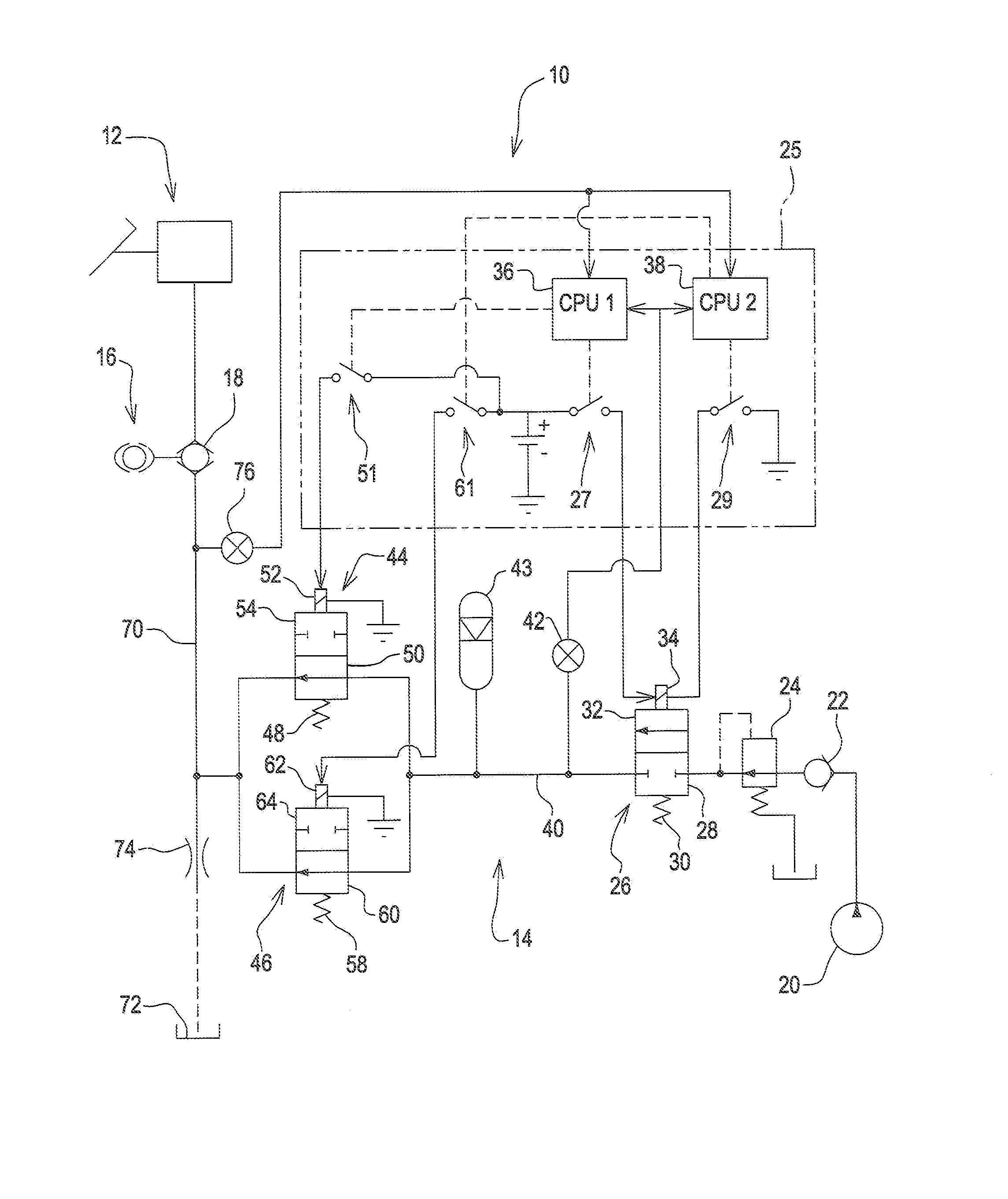
[0010]Referring to FIG. 1, a brake system 10 is provided for a vehicle (not shown) capable of manned and unmanned operation. The brake system 10 includes a conventional manually operated brake circuit 12 and an electro-hydraulic (E-H) brake circuit 14, both connected to a vehicle brake 16 through a shuttle valve 18 which communicates to the brake 16 the brake circuit 12 or brake circuit 14, whichever has the highest hydraulic pressure. The E-H brake system 14 is hydraulically plumbed in parallel with the manual brake system 12.

[0011]The E-H brake circuit 14 includes a pump 20 and a check valve 22 which permits one-way flow of brake fluid from the pump 20 to a pressure reducing valve 24. Valve 24 communicates fluid to a solenoid operated inlet valve 26. Valve 26 is biased into a normally closed position 28 by a spring 30 and is moved to an open position 32 by a solenoid 34.

[0012]Solenoid 34 is controlled by remote start controller (RSC) 25 which includes redundant central processing ...


PUM


Abstract

A brake control system is provided for a utility vehicle having manned and unmanned operational modes. The brake control system includes a hydraulically operated brake. A manually operated brake circuit and an electro-hydraulic (E-H) brake circuit are connected to the brake. The E-H brake circuit includes a pump, a solenoid operated inlet valve, an accumulator, and first and second solenoid operated brake valve connected between the brake and the inlet valve. A first CPU is operatively connected to the inlet valve and to the first brake valve. A second CPU is operatively connected to the inlet valve and to the second brake valve. An accumulator pressure sensor senses the accumulator pressure. A brake pressure sensor senses brake pressure. The first and second CPUs control the inlet valve and the brake valves as a function of the sensed accumulator pressure and brake pressure.

Description

FIELD OF THE INVENTION[0001]The present invention relates to a brake control system for a vehicle capable of both manned and unmanned operation.BACKGROUND OF THE INVENTION[0002]Some vehicles can be selectively controlled by an operator (manned) or autonomously controlled (unmanned). Such a dual mode vehicle must have a braking system which can safely control the vehicle in both situations. This requires a brake system which includes an electro-hydraulic (E-H) braking system which operates in parallel with the manual braking system. A control system with redundant central processing units (CPUs) has been proposed for use in such a vehicle. In such a vehicle, it is desired that E-H braking system meet two criteria. First, when in operating in autonomous mode, a single CPU must be able engage the brakes in the event of a single point failure. Otherwise, inability to bring the vehicle to a halt with the E-H braking system during unmanned operation may lead to an unsafe condition. Second...

Claims


Application Information

Patent Timeline
IPC IPC(8): B60T8/171
CPCB60T7/12B60T8/321B60T8/4809B60T2270/402B60T13/662B60T13/686B60T8/5012
Inventor REKOW, ANDREW KARL WILHELMSCHICK, TROY EUGENEVALLIERES, RICHARDDILLER, TIMOTHY
Owner DEERE & CO
Why Eureka
Try Eureka