Closed electrohydraulic controlling system

An electro-hydraulic control system, closed technology, applied in the direction of pump control, liquid variable capacity machinery, fluid pressure actuation device, etc., can solve the problems of heat generation and large energy consumption, achieve high energy efficiency, simple system, avoid The effect of throttling loss

Inactive Publication Date: 2006-08-16
TAIYUAN UNIV OF TECH
View PDF0 Cites 55 Cited by
  • Summary
  • Abstract
  • Description
  • Claims
  • Application Information

AI Technical Summary

Problems solved by technology

[0004] The purpose of a closed electro-hydraulic control system of the present invention is to provide a hydraulic pump that balances the flow difference of the differential cylinder in the hydraulic pump by redesigning the hydraulic pump flow plate or the suction and discharge chamber according to the area difference of the hydraulic cylinder. , only a very small hydraulic control check valve and accumulator to compensate the leakage of the pump and the compression of the oil can make the system operate normally, so that the hydraulic pump an...

Method used


Image

  • Closed electrohydraulic controlling system
  • Closed electrohydraulic controlling system
  • Closed electrohydraulic controlling system

Examples


Embodiment approach 1

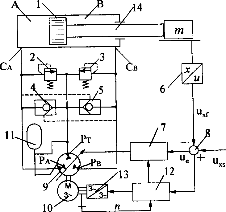
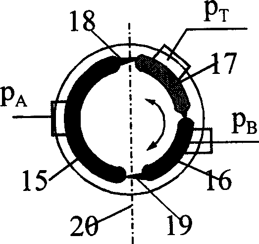
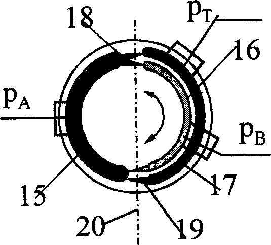
[0028] exist figure 1 In the embodiment shown, the hydraulic pump is a proportional or servo pump whose displacement can be continuously adjusted according to an electronic signal. figure 2 , image 3 Shown, after a special design. The oil port of the pump is changed from the traditional 2 oil ports for oil inlet and outlet to 3, and the oil port [p A ] is connected to the rodless cavity [A] of the hydraulic cylinder, and the oil port [p B ] communicates with the rod cavity [B] of the hydraulic cylinder, and the oil port [p T ] is connected with the low-pressure oil source [11]. The prime mover [10] can be an internal combustion engine, or an electric motor with adjustable speed, and it can be an AC asynchronous motor, an AC or DC servo motor, a switched reluctance motor, and the like. Speed ​​controller [13] can choose any form with mature technology at present. The sensor [6] can choose magnetostrictive type, inductive type, etc., that is, it can output analog signal ...

Embodiment approach 2

[0030] Such as Figure 4 shown, with figure 1 Compared with the scheme shown, the special feature is that the hydraulic pump adopts double-acting quantitative vane pump or motor, and the movement of the hydraulic cylinder can only be controlled by changing the speed of the motor. Therefore, there is only the controller [12] in the system without the controller [7]. The double-acting vane pump used has also been redesigned. Such as Figure 5 As shown, the inlet and outlet ports of the pump are changed from 2 to 3. Among them, the oil outlet of the pump [p A ] unchanged, it is connected to the rodless cavity [A] of the hydraulic cylinder when working. The suction port of the pump is divided into [p B ] and [p T ]2 separate ports, [p B ] port is connected with the rod cavity [B] of the hydraulic cylinder, [p T ] port is equivalent to the oil suction port of the original pump and communicates with the low-pressure oil source [11].

Embodiment approach 3

[0032] Such as Figure 6 As shown, in this case, the prime mover [10] of the system chooses an internal combustion engine or an electric motor with constant speed. The hydraulic pump is the same as that used in Example 1, which is a newly designed axial piston pump. The difference between the two schemes is that scheme 3 has no speed controller [13] and controller [12]. The system controls the movement direction, speed and position of the hydraulic cylinder by changing the displacement of the hydraulic pump.


PUM


Abstract

A closed electro-hydraulic control system comprised a differential hydraulic cylinder, two safety valves, a small path fluid one-way valve, a displacement transducer, a subtractor, two controllers, a hydraulic pump, a prime motor, a low-pressure oil-supply system and a rotational speed governor. The hydraulic pump has three oil ports connected with a rod-free cavity, a rod cavity of the differential hydraulic cylinder and the low-pressure oil-supply system separately.

Description

1. Technical field: [0001] The present invention is a closed electro-hydraulic control system, belonging to the field of electro-hydraulic control, specifically a hydraulic pump (traditional servo or proportional pump, variable speed pump) to continuously control the movement speed, direction and position of a differential hydraulic cylinder device. 2. Background technology: [0002] There are two types of electro-hydraulic control systems: volume control and throttling (valve control). The traditional view is that throttling control technology is used in small and medium power systems that require high dynamic response, while volume control technology is used in high power systems. The biggest disadvantage of the throttling control electro-hydraulic system is that there is a large throttling loss, the system energy efficiency is low and the system heats up. Therefore, the new development direction is to directly control the movement of the hydraulic cylinder with the hydr...

Claims


Application Information

Patent Timeline
IPC IPC(8): F04B49/00F04C14/00F15B15/18
Inventor 权龙李凤兰
Owner TAIYUAN UNIV OF TECH
Why Eureka
Try Eureka