Electro-hydraulic power unit with a rotary cam hydraulic power unit

Inactive Publication Date: 2007-02-27
SAUER DANFOSS NORDBERG
View PDF15 Cites 53 Cited by
  • Summary
  • Abstract
  • Description
  • Claims
  • Application Information

AI Technical Summary

Benefits of technology

[0014]An electro-hydraulic power unit is disclosed that includes a housing filled with hydraulic fluid. A hydraulic power unit is disposed within the housing, the power unit having a mechanical power shaft. Additionally, an electric machine is disposed within the housing adjacent to the hydraulic power unit, the electric machine having a rotor secured to the mechanical power shaft of the hydraulic power unit. Hydraulic fluid within the housing passes over the electric machine, thus cooling the electric machine and providing for improved efficiency and performance.

Problems solved by technology

Advantages and disadvantages of this design are apparent to persons skilled in the art.

Method used


Image

  • Electro-hydraulic power unit with a rotary cam hydraulic power unit
  • Electro-hydraulic power unit with a rotary cam hydraulic power unit
  • Electro-hydraulic power unit with a rotary cam hydraulic power unit

Examples


Embodiment Construction

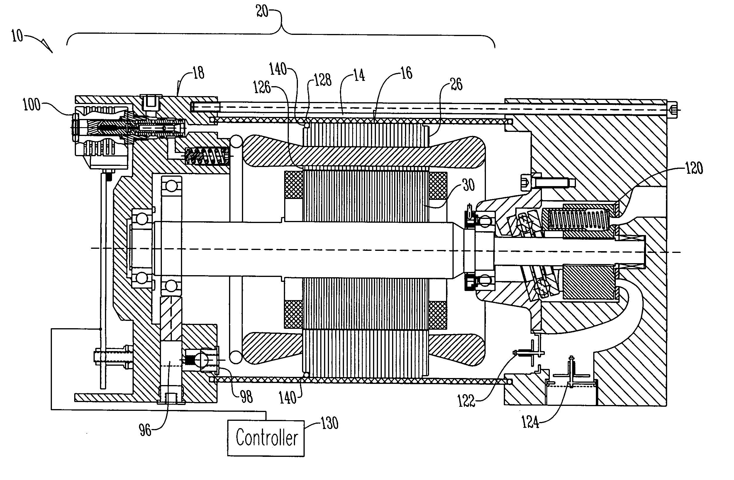
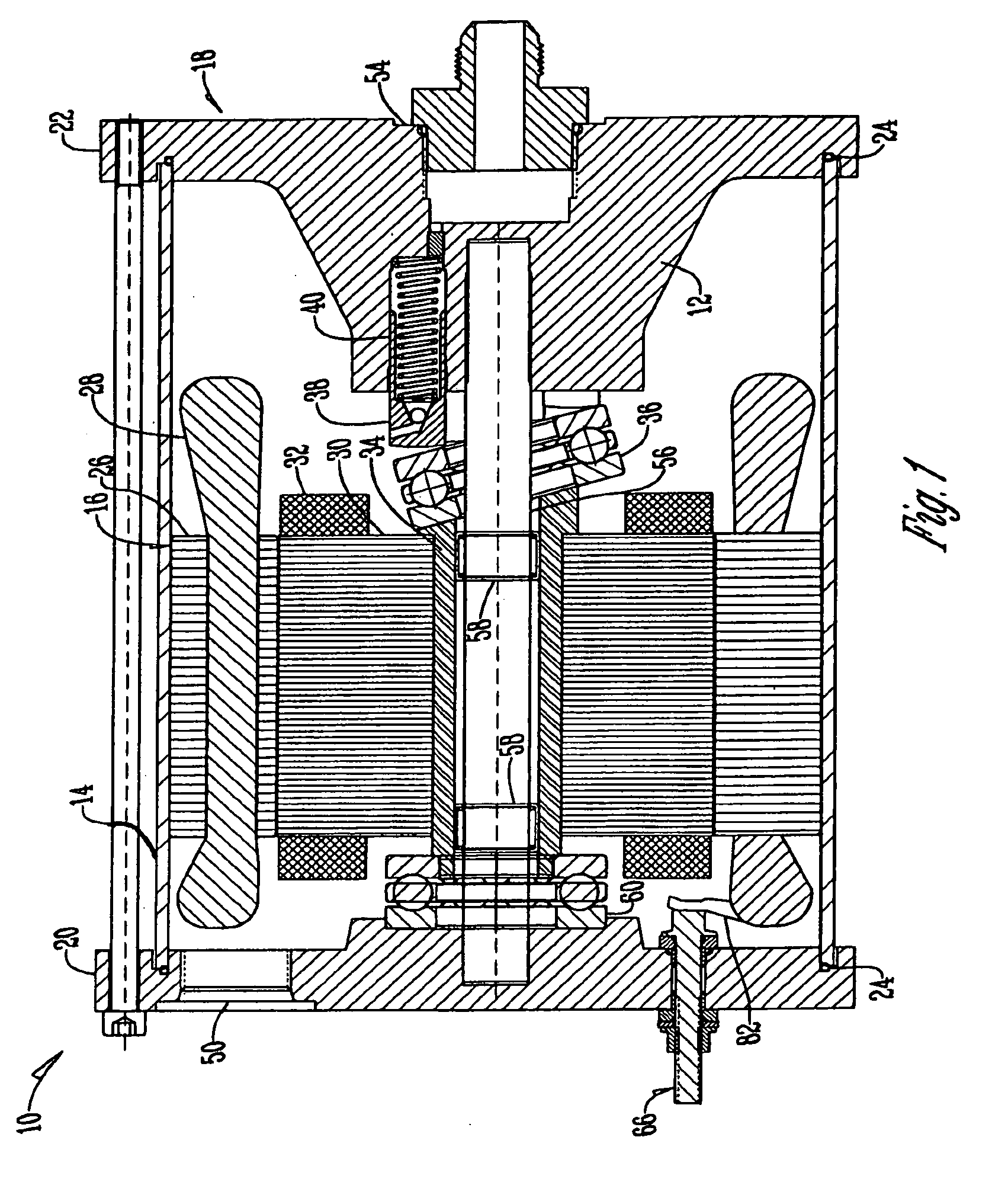
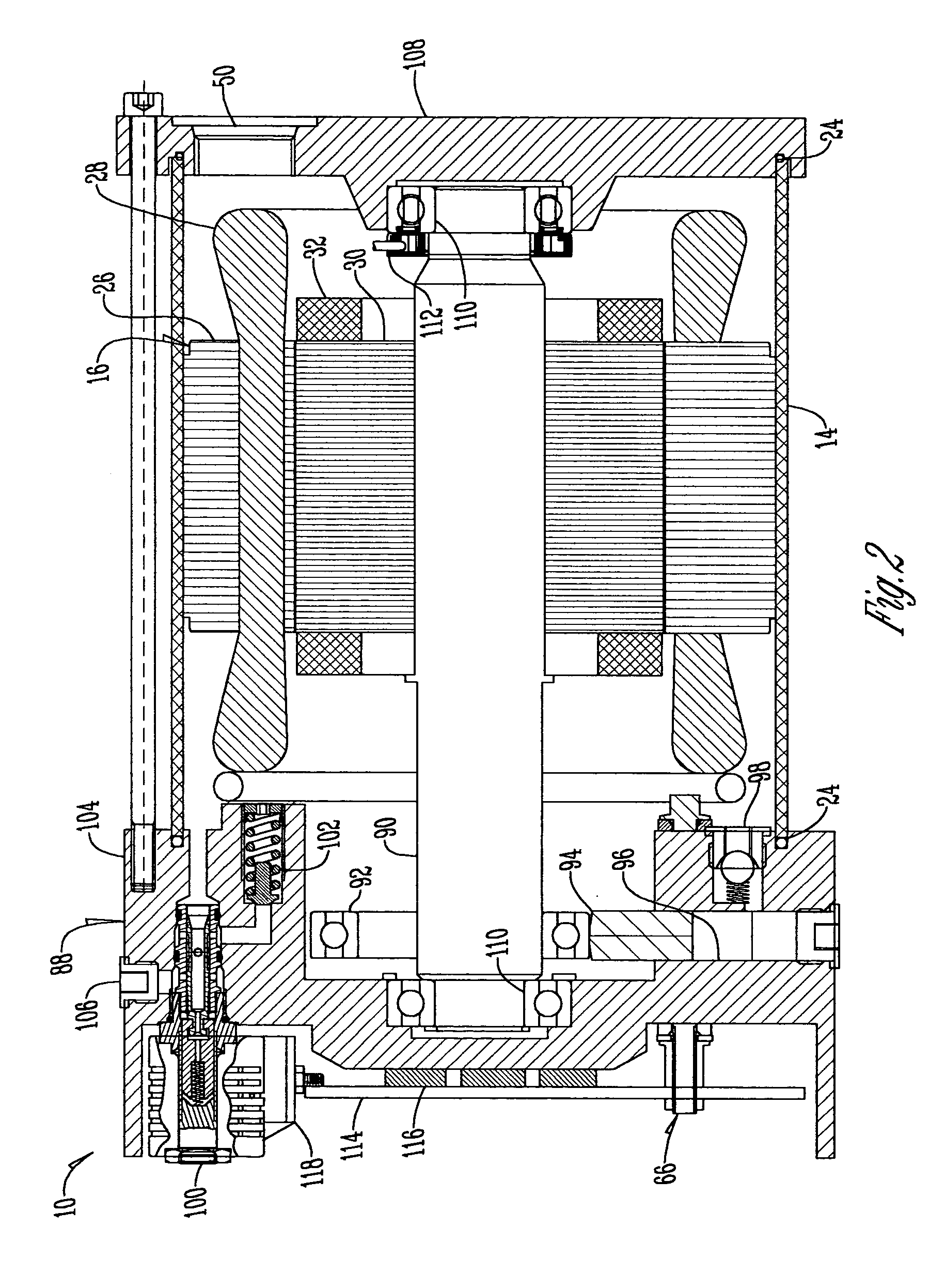
[0024]With reference to FIG. 1, an electro-hydraulic power converter 10 is disclosed with a rotary cam hydraulic power unit 12. This unit 12 includes a housing 14, an electric machine 16, and a hydraulic machine 18.

[0025]The housing 14 preferably is a steel tube and is substantially flooded with hydraulic fluid. End caps 20 and 22 are fitted against housing 14, thus forming a complete housing for the rotary cam hydraulic power unit 12. The tube is preferably sealed to the end caps with one or more elastomeric O-rings 24.

[0026]The electric machine 16, which also is known as an electric power means, preferably is an alternating current (AC) induction motor, but may be any conventional electric machine, including: an alternating current (AC) machine; a direct current (DC) machine; an induction machine; a single phase machine; a three phase machine; a polyphase machine; a switched reluctance machine; a written pole machine; a permanent magnet alternating current (PMAC) machine; a perman...


PUM


Abstract

An electro-hydraulic power unit is disclosed that includes a housing filled with hydraulic fluid. A hydraulic power unit is disposed within the housing, the power unit having a mechanical power shaft. Additionally, an electric machine is disposed within the housing adjacent to the hydraulic power unit, the electric machine having a rotor secured to the mechanical power shaft of the hydraulic power unit. Hydraulic fluid within the housing passes over the electric machine, thus cooling the electric machine and providing for improved efficiency and performance.

Description

CROSS REFERENCE TO A RELATED APPLICATION[0001]This application is a continuation of U.S. Provisional Patent Application Ser. No. 60 / 542,379 filed Feb. 6, 2004.BACKGROUND OF THE INVENTION[0002]The present invention relates to an electrical-hydraulic fluid power converter. More specifically, the present invention relates to a device that includes an electric machine coupled to a hydraulic machine.[0003]In material handling and other related fields, lift trucks are often used for transporting heavy materials. Such trucks often use a large lead acid storage battery or similar device as a source of electrical power. Lift trucks also typically use a system of hydraulic cylinders for the purpose of raising, lowering, tilting, reaching, shifting, and other load manipulation functions. With conventional trucks, it is common to use a battery powered electric motor to turn a hydraulic pump. With this system, hydraulic pressure and flow are produced by the pump and are modulated through a syste...

Claims


Application Information

Patent Timeline
Patent Type & Authority Patents(United States)
IPC IPC(8): F04B17/03H02K9/19F04B1/12F04B23/00F04B1/14F04B17/00F04B17/04F04B23/02F04B53/08F16H61/26H02K5/20H02K7/14
CPCF04B1/14F04B1/145F04B17/03H02K5/20H02K7/14H02K9/19F04B23/021H02K2205/12H02K5/203
Inventor GANDRUD, MICHAEL D.FREDERIKSEN, TORBENESDERS, HANS
Owner SAUER DANFOSS NORDBERG
Why Eureka
Try Eureka