Brake Control Device

a technology of brake control and control device, which is applied in the direction of brake action initiation, brake system, vehicle components, etc., can solve problems such as loss of operation, and achieve the effect of improving the loadability of the vehicl

Active Publication Date: 2011-12-29
HITACHI ASTEMO LTD
View PDF9 Cites 35 Cited by
  • Summary
  • Abstract
  • Description
  • Claims
  • Application Information

AI Technical Summary

Benefits of technology

[0011]The present invention is advantageous in terms of the improvement of loadability of the vehicle.
[0012]In addition to the above object, different objects sought to be achieved for commercialization of of the present invention have been realized in the embodiments described below. Such objects include the improvement of safety, reliability, and the like.

Problems solved by technology

Thus, if there is a malfunction of a vehicle power supply source, it results in loss of operation.

Method used


Image

  • Brake Control Device
  • Brake Control Device
  • Brake Control Device

Examples


embodiment 1

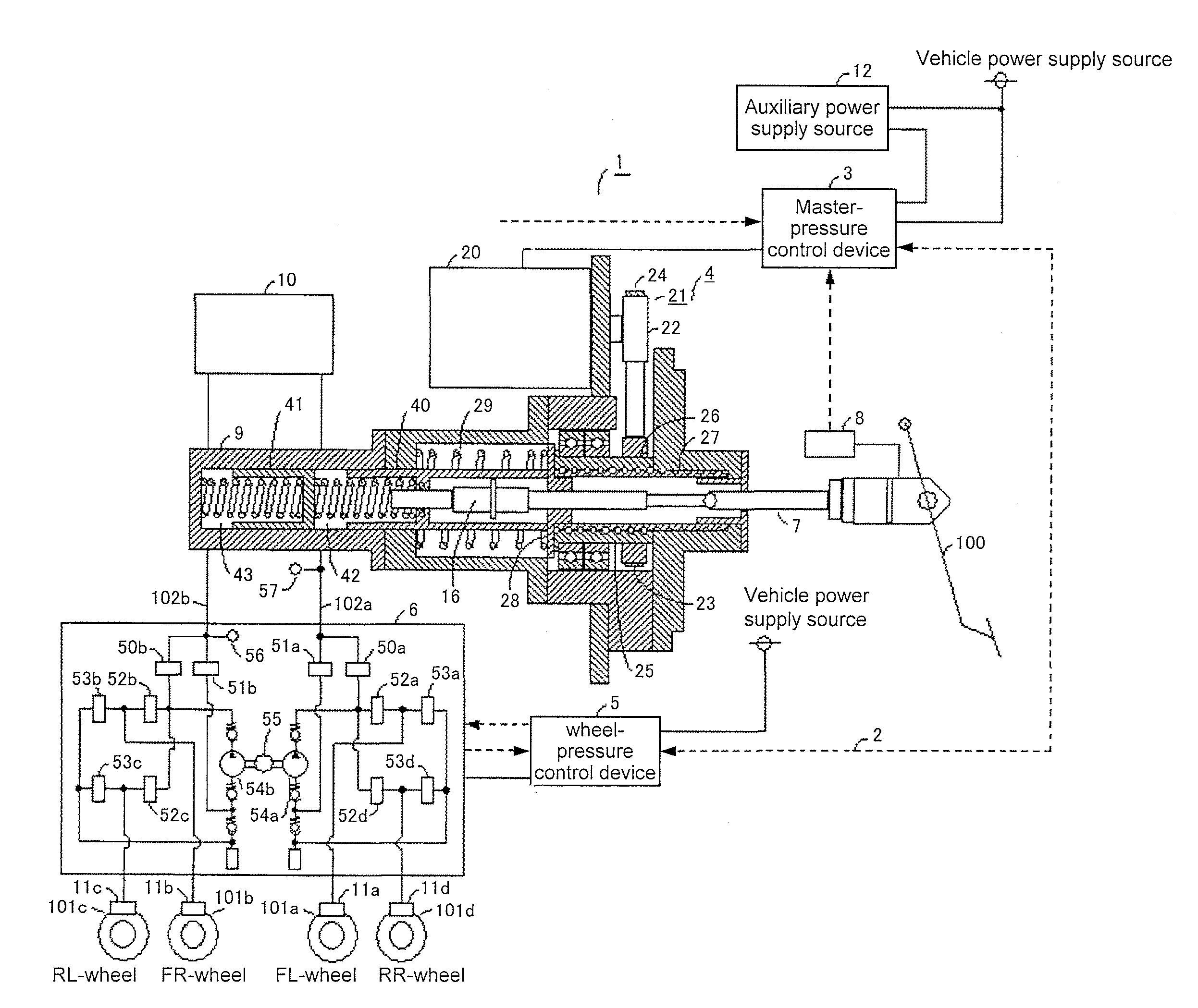
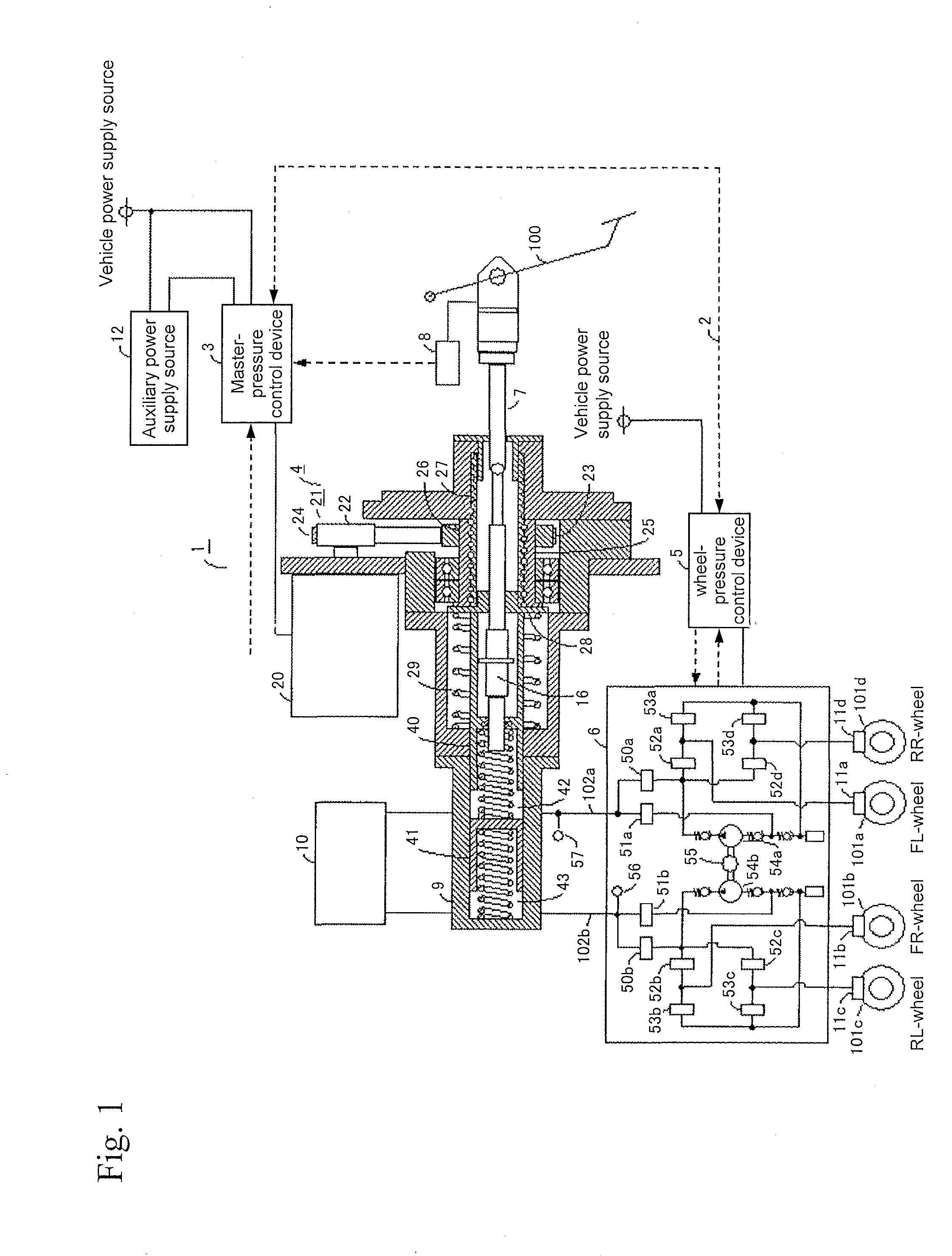
[0023]FIG. 1 is a block diagram illustrating an overall configuration of the brake control device. In FIG. 1, the arrowed dash lines represent signal lines, and the arrows indicate the direction in which their respective signals flow. A brake control system 1 comprises a master-cylinder pressure controlling mechanism 4 provided with an electric motor 20 for controlling master-cylinder pressure that is output pressure from a master cylinder 9, a master-cylinder pressure control device 3 for electrically controlling the master-cylinder pressure controlling mechanism 4, a wheel-cylinder pressure controlling mechanism 6, a wheel-cylinder pressure control device 5 for electrically controlling the wheel-cylinder pressure controlling mechanism 6, an input rod 7, an operational degree detecting device 8, a master cylinder 9, a reservoir tank 10, and an auxiliary power supply source 12. A first pressurizing-depressurizing unit for changing output pressure from the master cylinder 9 has an in...


PUM


Abstract

According to the present invention, limited electric power is consumed so as to achieve long-lasting use of electric power during brake control with the use of an auxiliary power supply source when there is a malfunction of a vehicle power supply source. In addition, a brake control device for ensuring responsivenss at the beginning of braking or when emergency braking is necessary is provided. The brake control device of the present invention is a brake control device for detecting electric signals generated depending on the degree of brake-pedal operation and calculating the driver's demanded braking force based on the electric signals so as to generate the demanded braking force, which comprises an auxiliary power supply source for supplying electric power to the brake control device when there is a malfunction of a vehicle power supply source and controls braking deppending on the charged capacity of the auxiliary power supply source.

Description

TECHNICAL FIELD[0001]The present invention relates to a brake control device of a vehicle, and more particularly to a brake control device of a vehicle to generate either a braking force or an assisting force corresponding to the degree of brake-pedal operation.BACKGROUND ART[0002]In recent years, brake control devices of vehicles have been studied in which a braking force is assisted by electric power used as a drive force in response to brake-pedal operation. Such brake control devices are operated by supplying electric power from vehicle power supply sources. Thus, if there is a malfunction of a vehicle power supply source, it results in loss of operation. In order to cope with loss of operation, a brake control device that is electrically operated has a mechanical configuration in which a brake pedal depressing force is transmitted to the braking system of each wheel to cause generation of a braking force.[0003]However, it is desirable for such brake control device to use electr...

Claims


Application Information

Patent Timeline
Patent Type & Authority Applications(United States)
IPC IPC(8): B60T13/74
CPCB60T7/042B60T8/321B60T13/745B60T8/4872B60T8/96B60T8/442B60T8/885
Inventor NISHINO, KIMIOINNAMI, TOSHIYUKIMATSUZAKI, NORIKAZUKIKAWA, MASAYUKIMIYAJIMA, AYUMUAJIMA, TOSHIYUKI
Owner HITACHI ASTEMO LTD
Why Eureka
Try Eureka