Charge Control System

a control system and charge technology, applied in the direction of battery/fuel cell control arrangement, secondary cell servicing/maintenance, battery/motor energy reduction, etc., can solve the problems of shortening not necessarily low temperature, and reducing the energy that can be used for driving the electric motor. , to achieve the effect of increasing the cruising distance of the electric vehicl

Inactive Publication Date: 2011-12-29
HITACHI LTD
View PDF1 Cites 65 Cited by
  • Summary
  • Abstract
  • Description
  • Claims
  • Application Information

AI Technical Summary

Benefits of technology

[0027]According to the present invention, the cruising distance of an electric vehicle can be increased by appropriately controlling the temperature of the battery when the electric vehicle is run immediately after completion of charging.

Problems solved by technology

However, due to heat generation caused by the discharge current accompanying the start of running of the electric vehicle, it may happen that the cooler is operated immediately after the start of running.
As a result, energy that can be used for driving the electric motor is reduced and this shortens a cruising distance of the electric vehicle.
However, the battery temperature is not necessarily low after completion of charging, and when the electric vehicle starts running immediately after charging, it is conceivable that cooling by using battery power becomes necessary at once.
In such a case, operation of the cooler reduces energy that can be used for driving the electric motor and hence there arises a problem that the cruising distance of the electric vehicle is shortened.

Method used


Image

  • Charge Control System
  • Charge Control System
  • Charge Control System

Examples


first embodiment

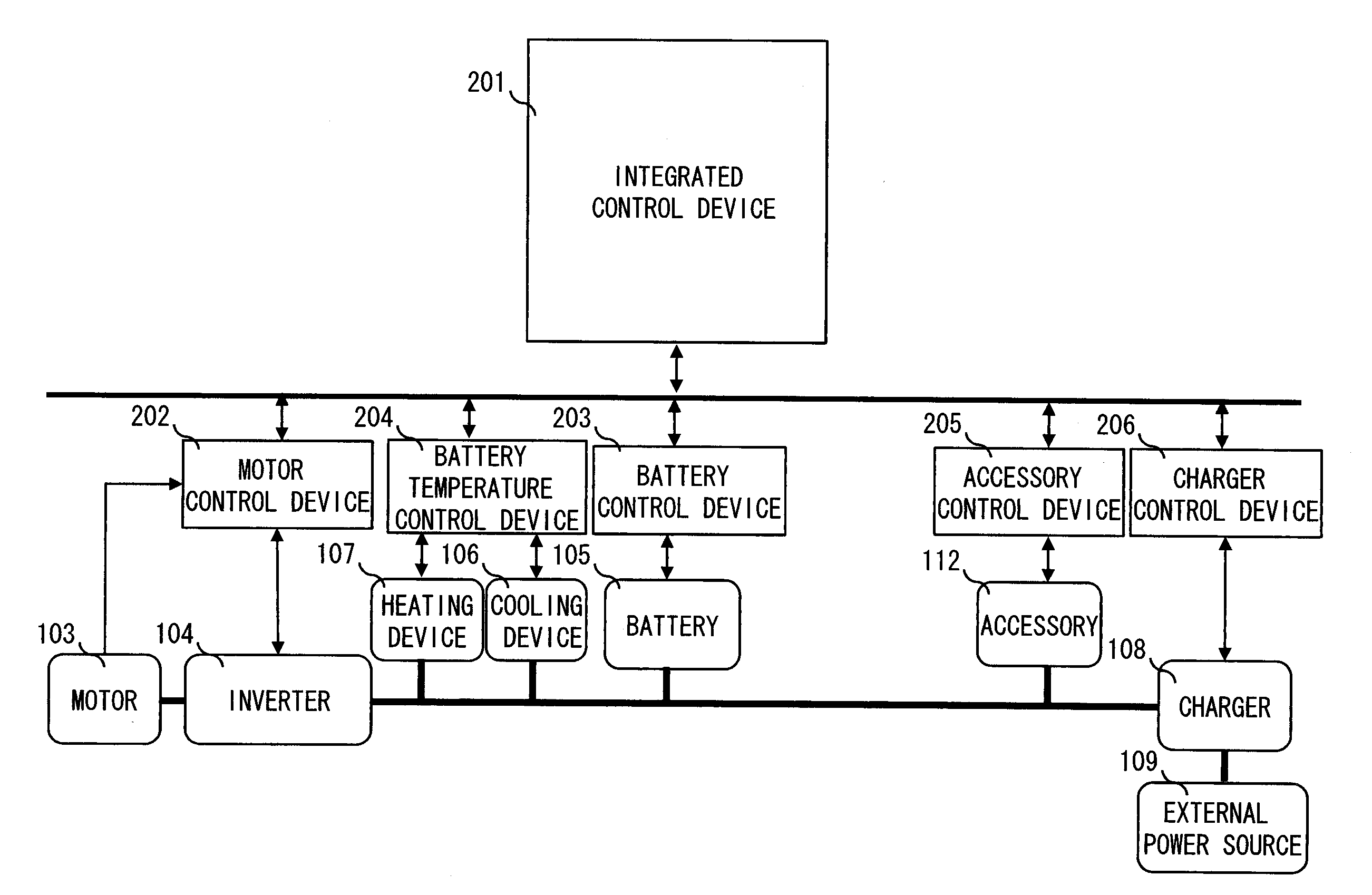
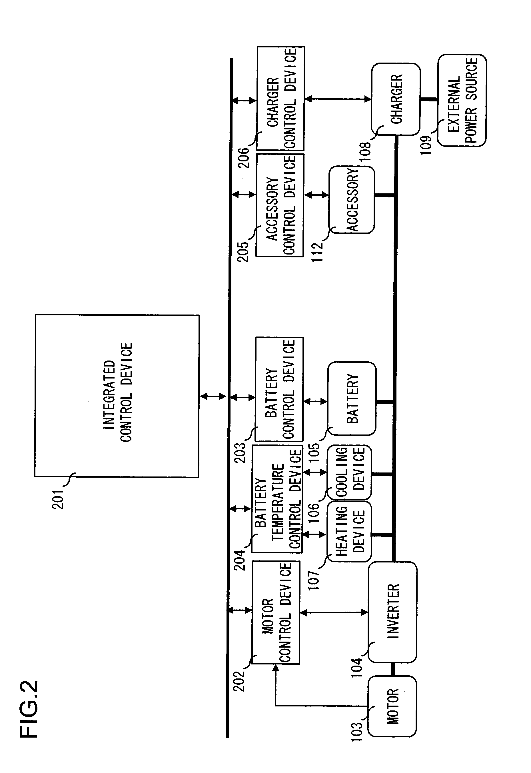
[0054]FIG. 2 presents a diagram showing the construction of the charge control system according to the first embodiment of the present invention. The charge control system includes an integrated control device 201; a motor control device 202 for controlling the inverter 104 and the motor 103; a battery control device 203 for controlling the battery 105; a battery temperature control device 204 for controlling the cooling device 106 and the heating device 107; an accessory control device 205 for controlling an accessory 112; and a charger control device 206 for controlling the charger 108. These control devices are mutually connected through a communication network, for example, CAN (Controller Area Network) provided in the electric vehicle 101.

[0055]In the charge control system shown in FIG. 2, the inverter 104, the cooling device 106, the heating device 107, the accessory 112, and the charger 108, respectively, are connected to the battery 105. As a result, the power from the batte...

second embodiment

[0096]Next, the charge control system according to a second embodiment of the present invention is explained. The present embodiment is different from the first embodiment in that in the second charging mode in step S402 illustrated in FIG. 4, control is performed such that the battery temperature T is not set at the lower limit value Tmin of the charge-discharge allowing battery temperature but at a target battery temperature T_target that is set taking into consideration an outside air temperature T_out. The target battery temperature T_target is obtained by adding an offset temperature delta_T determined depending on the outside air temperature T_out to T_min.

[0097]FIG. 9 presents a flowchart illustrating processing in a second charging mode performed in the charge control system according to the second embodiment instead of the processing illustrated by the flowchart in FIG. 7. In the flowchart in FIG. 9, like FIG. 7, the processing steps having the same contents as those shown ...

third embodiment

[0119]Next, the charge control system according to a third embodiment of the present invention is explained below. The present embodiment is different from the second embodiment as explained above in that in step S902 in FIG. 9, the offset temperature delta_T is determined based on a forecasted load of the battery 105 and the outside air temperature T_target and the target battery temperature T_target is calculated.

[0120]FIG. 13 presents a construction diagram that shows the charge control system according to the third embodiment of the present invention. Compared with the charge control system shown in FIG. 2, the charge control system of the present embodiment includes a vehicle circumference information obtaining device 1301, an information communicating device 1302 and, in the integrated control device 201, LUT (Look Up Table) 1303 that indicates relationships among the forecasted load of the battery 105, the outside air temperature T_out, and the offset temperature delta_T.

[012...


PUM

PropertyMeasurementUnit
temperatureaaaaaaaaaa
cooling capacityaaaaaaaaaa
heating capacityaaaaaaaaaa

Abstract

The charge control system includes at least a battery temperature control device, a cooling device, a heating device, and an integrated control device. The battery control device detects SOC of a battery. Based on the detected SOC, the integrated control device switches between a first charging mode in which the battery is charged at a substantially constant current and a second charging mode in which the battery is charged at a substantially constant voltage. In the second charging mode, the battery temperature control device performs rapid cooling control to control the cooling device such that it has a cooling capacity in the second charging mode higher than a cooling capacity in the first charging mode. Thus, the battery temperature is appropriately controlled to increase a cruising distance even when the electric vehicle is run immediately after completion of charging.

Description

INCORPORATION BY REFERENCE[0001]The disclosure of the following priority application is herein incorporated by reference: Japanese Patent Application No. 2010-147415 filed Jun. 29, 2010.BACKGROUND OF THE INVENTION[0002]1. Field of the Invention[0003]The present invention relates to a charge control system for an electric vehicle that is mounted on the electric vehicle and controls a charge current from an external power source to an in-vehicle battery on the electric vehicle.[0004]2. Description of Related Art[0005]Generally, an electric motor is used as a drive source for electric vehicles to which power can be supplied from an external power source and the electric vehicles are each equipped with an in-vehicle battery for driving the electric motor. The in-vehicle battery generates heat upon charge and discharge so that the temperature of the battery or battery temperature increases. However, depending on the outside air temperature and operation conditions, it may happen that the...

Claims


Application Information

Patent Timeline
Patent Type & Authority Applications(United States)
IPC IPC(8): H02J7/00B60L11/18H01M10/42H01M10/44H01M10/46H01M10/48H01M10/60H01M10/613H01M10/615H01M10/625H01M10/633H01M10/635H01M10/6571H01M10/6572H01M10/663H02J7/04H02J7/10
CPCB60L1/003Y02T10/7291B60L11/1816B60L11/1874B60L11/1875B60L2240/545B60L2240/662Y02T10/7011Y02T90/14Y02T90/16Y02T10/7005Y02T10/705H01M10/44H01M10/48H01M10/5004H01M10/5006H01M10/5016H01M2220/20B60L11/1803H01M10/625H01M10/615H01M10/613B60L50/51B60L58/26B60L58/27Y02T10/70Y02T10/72Y02E60/10B60L3/0046B60L3/04Y02T10/7072
Inventor INABA, RYOTASHIRO, NAOYUKI
Owner HITACHI LTD
Why Eureka
Try Eureka