Fluid Flow Rate Compensation System Using an Integrated Conductivity Sensor to Monitor Tubing Changes

a technology of conductivity sensor and flow rate compensation, which is applied in the field of pumps, can solve the problems of affecting the pump flow rate, reducing volume fraction and increasing densification, and small effect, and achieves the effect of compensating for degradation or wear

Active Publication Date: 2011-12-29
ICU MEDICAL INC
View PDF18 Cites 31 Cited by
  • Summary
  • Abstract
  • Description
  • Claims
  • Application Information

AI Technical Summary

Benefits of technology

[0017]An infusion system is disclosed that monitors variations over time of properties of a section of tubing acted upon by a pump and uses a controller and algorithm to compensate for such variations to provide a consistent rate of fluid flow from the pump. A first embodiment of such an infusion system utilizes a force sensor that engages the tubing wherein an actuating device forces the force sensor against the tubing to compress the tubing. A sensing device is then provided to monitor the actuating device in order to determine characteristics of the actuating device. The sensor and sensing device are electrically connected to a controller of the pump to provide compression information regarding the tubing so that an algorithm can control the fluid flow rate through the tubing as the tubing changes over time.
[0018]In a second embodiment the infusion system presented also ha

Problems solved by technology

It is known in polymer chemistry that as polymers degrade due to mechanical, environmental, or aging effects their polymer chains begin to break down, which results in a volume fraction decrease and increased densification.
Even a piece of tubing sitting on the shelf will change over time and could affect the pump flow rate once installed in the pump.
However, this effect is relatively small compared to mechanical degradation caused by the pump.
Typically, for a given mechanism speed, flow rate begins to diminish over time as tubing wears.
While these present one so

Method used


Image

  • Fluid Flow Rate Compensation System Using an Integrated Conductivity Sensor to Monitor Tubing Changes
  • Fluid Flow Rate Compensation System Using an Integrated Conductivity Sensor to Monitor Tubing Changes
  • Fluid Flow Rate Compensation System Using an Integrated Conductivity Sensor to Monitor Tubing Changes

Examples


Embodiment Construction

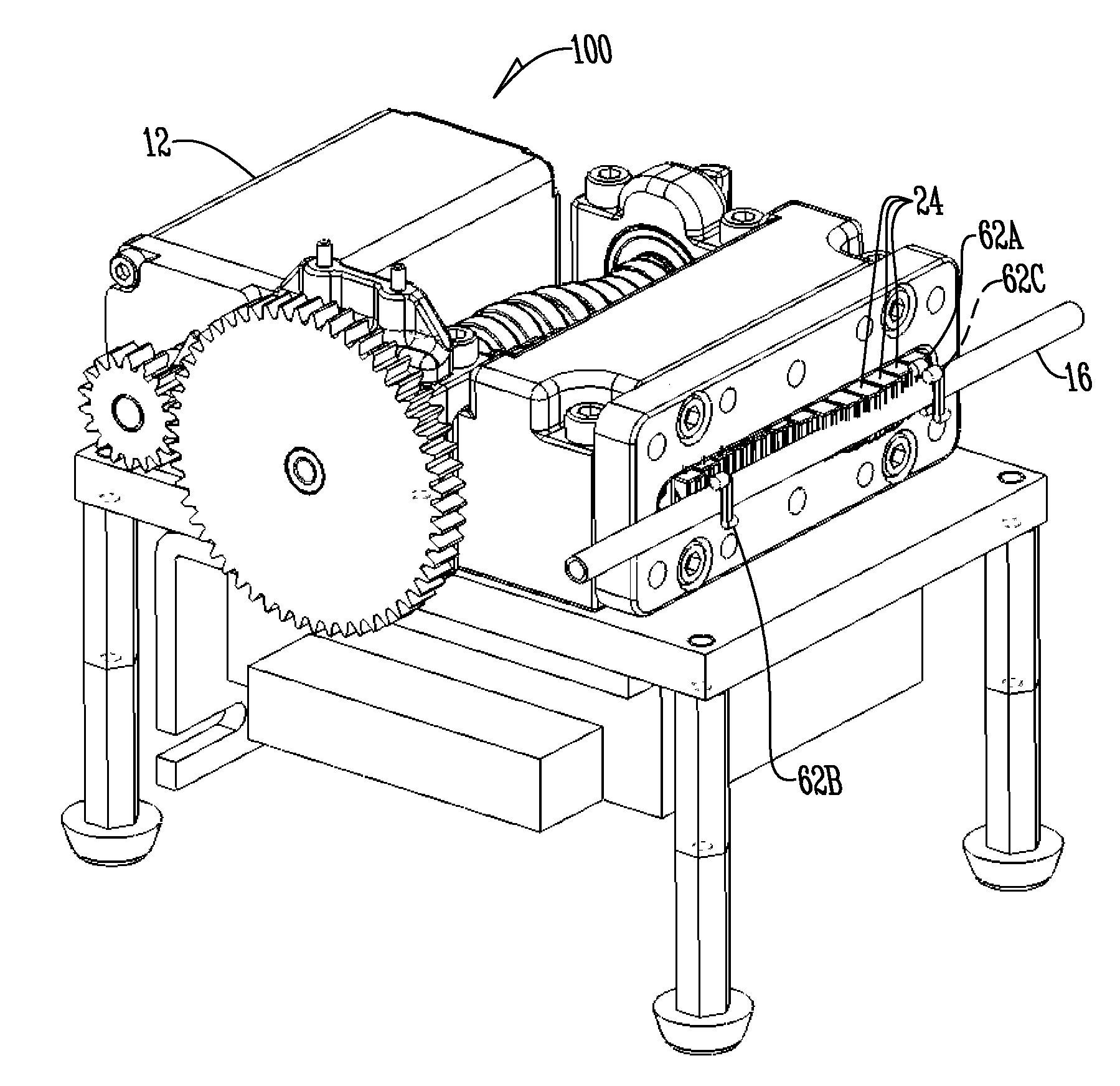
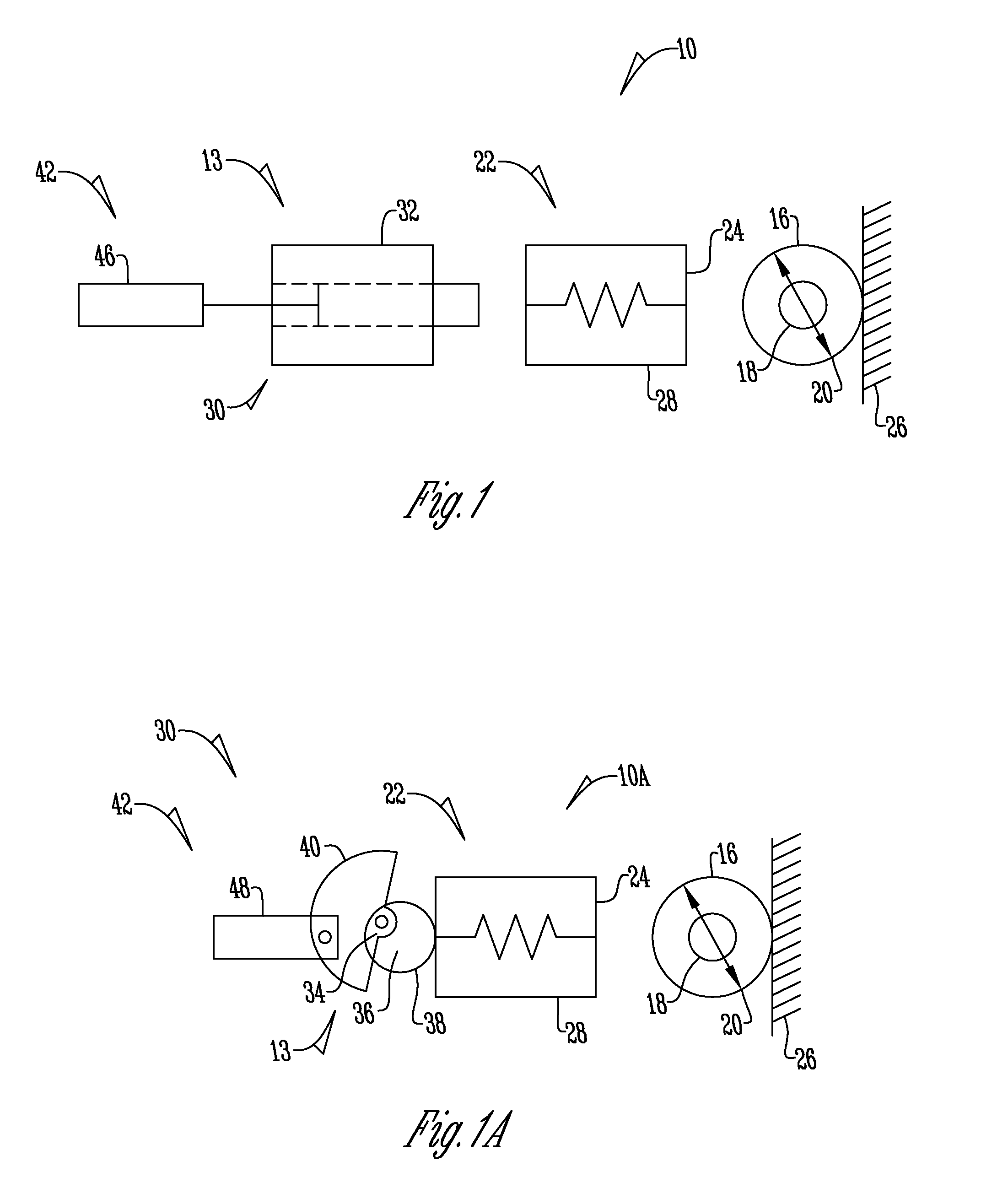
[0030]The figures illustrate the invention in the context of infusion systems 10, 10A, 100; however the invention has applicability to other infusion systems and fluid handling systems as well. As generally depicted in FIG. 9, the infusion systems 10, 10A, 100 utilize a pump 12 that in one embodiment is a peristaltic pump that includes a controller 14 that contains an algorithm to adjust fluid flow by operating a motor 9 that manipulates or operatively engages via a pumping mechanism 13 a section of tubing 16 through which fluid flows. The tubing 16 can be of any shape, including the standard circular or alternatively hexagonal, square or the like. The tubing 16 has an inner diameter 18 and outer diameter 20 and in addition has a predetermined ovality, modulus of elasticity and other such inherent characteristics. The tubing 16 may be any type of material including PVC, a polymer composite, a conductive polymer composite (CPC) or the like.

[0031]FIGS. 1 and 1A show two different embo...


PUM


Abstract

An infusion system and method for controlling the fluid flow from a pump includes a pump system that has a controller that utilizes an algorithm to control the flow rate of fluid through tubing. A plurality of electrodes operatively contacts an electrically conductive portion of the tubing that is also acted upon by the pump system. The electrodes monitor electrical properties of the tubing and provide an electric signal indicative thereof to the controller, which varies the flow rate of the fluid through the tubing as a result of the electric signal.

Description

CROSS REFERENCE TO RELATED APPLICATION[0001]This application claims the benefit of U.S. Provisional Application No. 61 / 357,660 filed Jun. 23, 2010.BACKGROUND OF THE INVENTION[0002]This invention relates to pumps for delivery of fluids to a patient. More specifically this invention relates to a fluid flow rate compensation system that monitors the tubing used in a pump in order to control the fluid flow rate of the pump or ascertain information about the fluid in the tubing.[0003]Peristaltic pumps provide a pumping mechanism that pumps fluid through tubing by flexing or compressing the tubing repeatedly to achieve a desired flow rate. The flexing of the tubing induces wear that changes the geometric and mechanical properties of the tubing (e.g. elastic modulus, tan delta, wall thickness, diameters, etc.). These tubing properties directly impact the amount of fluid delivered in a pump stroke. Therefore by monitoring and understanding how the tubing is changing over time or over a plur...

Claims


Application Information

Patent Timeline
IPC IPC(8): F04B49/00
CPCA61M5/168F04B43/0072F04B49/065F04B43/12F04B43/0081
Inventor JOHNSON, THOMAS D.BRUMUND, RYAN R.MCNEELY, JAMES A.
Owner ICU MEDICAL INC
Why Eureka
Try Eureka