
Adaptive power and thermal management system

a technology of thermal management system and adaptive power, which is applied in the direction of domestic cooling equipment, energy-efficient board measures, lighting and heating equipment, etc., can solve the problems of complex design, low efficiency of thermal management equipment, and the complexity of engine configuration, and achieve the effect of increasing the heat sink capacity of the fuel tank

Active Publication Date: 2012-01-05
GENERAL ELECTRIC CO
View PDF7 Cites 63 Cited by
  • Summary
  • Abstract
  • Description
  • Claims
  • Application Information

AI Technical Summary

Benefits of technology

[0012]An air cycle machine engine control may be used for providing on-demand cooling for one or more of the aircraft components by increasing heat sink capacity of the fuel tanks and controlling a flow rate and pressure of the pressurized air into the power turbine and the combustor.

Problems solved by technology

The inventors of 7,624,592 found that these designs were complex and wanted to reduce the complexity of the engine configuration and its integrated power and cooling systems.
Current thermal management systems do not supply such large amounts of cooling power.
Bursts of high cooling loads or power are required during high powered flight and directed energy weapon operation.

Method used


Image

  • Adaptive power and thermal management system
  • Adaptive power and thermal management system
  • Adaptive power and thermal management system

Examples


Embodiment Construction

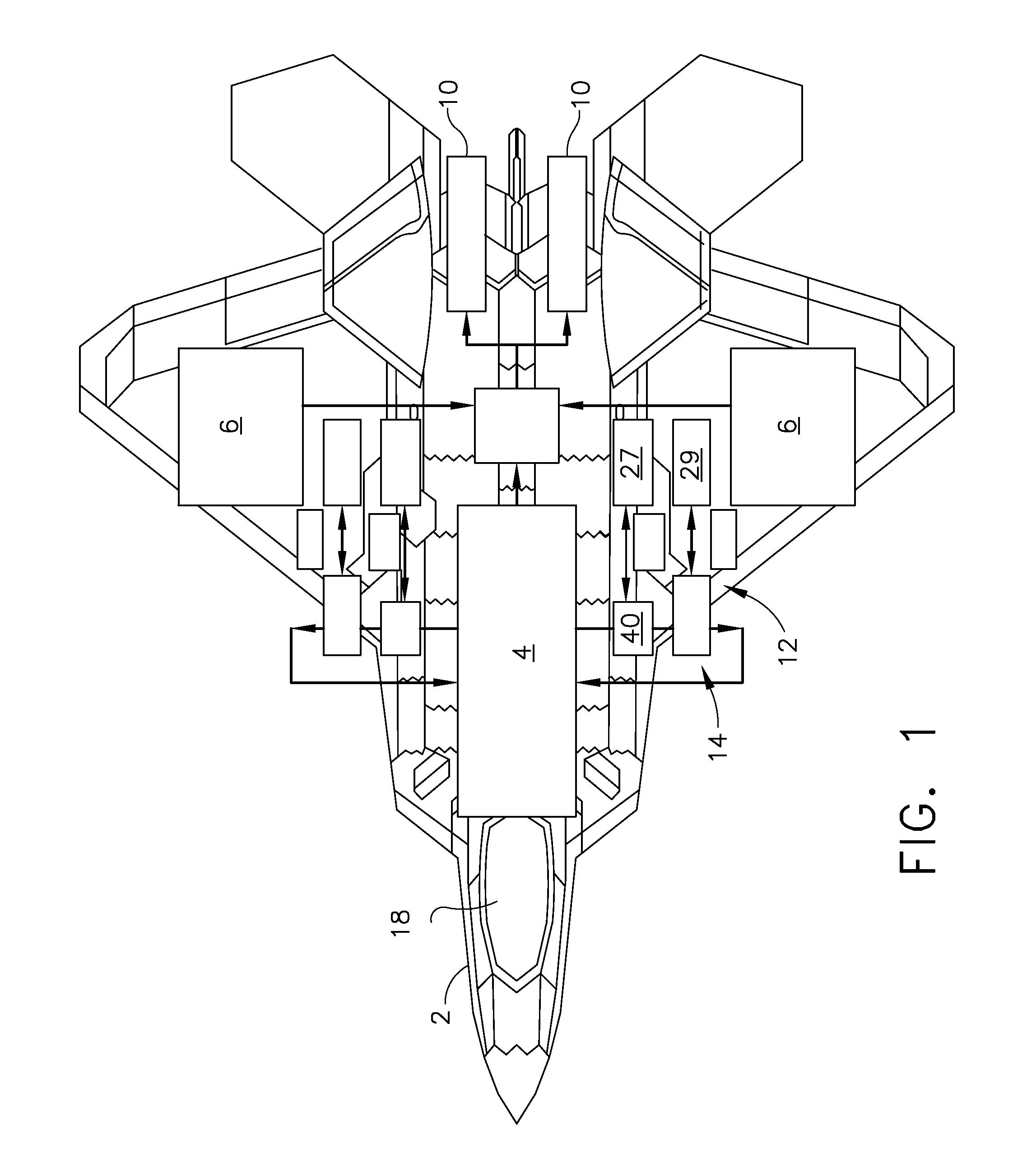
[0020]Illustrated diagrammatically in FIG. 1 is an exemplary gas turbine engine powered aircraft 2 having dual turbofan aircraft gas turbine engines 10 and an internal fuel tank(s) 4 and two wet wing fuel tanks 6 for storing aircraft fuel 11. The wing fuel tanks 6 are referred to as being wet because they are housed in the wings and subject to cooling and heating of ambient air through which the aircraft flies. The aircraft includes an adaptive power thermal management system (APTMS) 12 powered by one or both of the gas turbine engines 10.

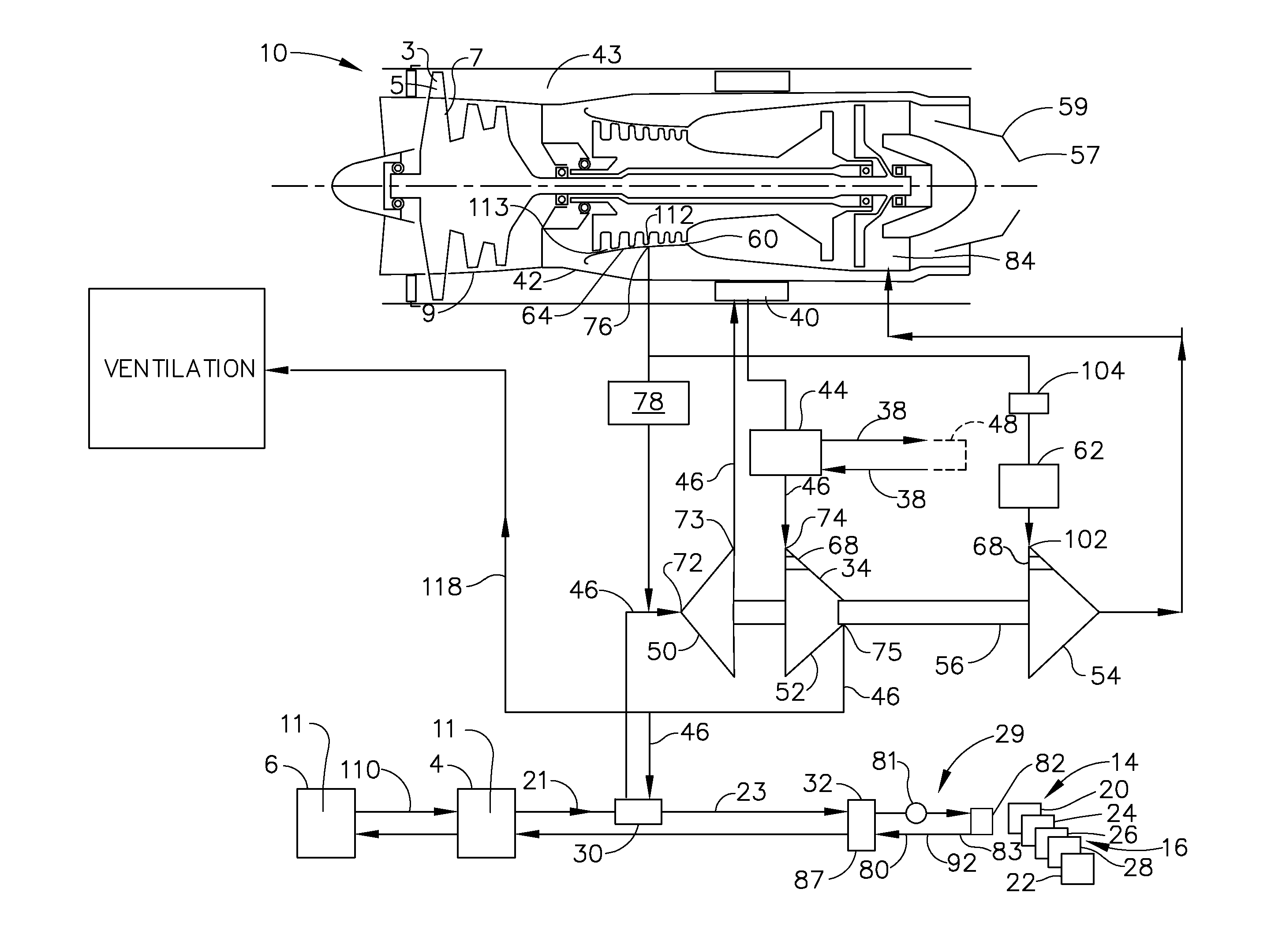
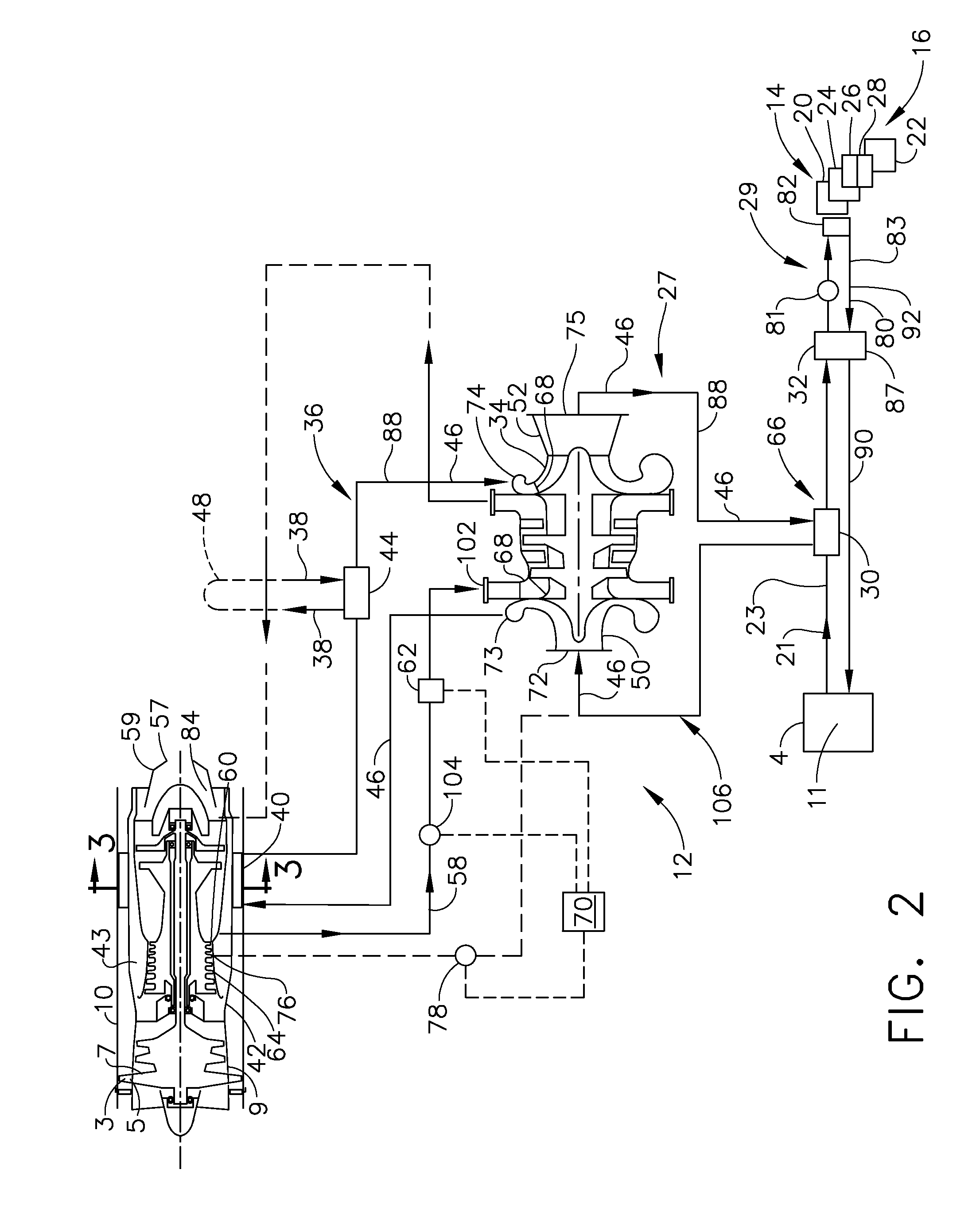
[0021]Referring to FIGS. 1 and 2, the adaptive power thermal management system (APTMS) 12 includes an environmental control system (ECS) 14 to provide cooling for liquid and air cooled aircraft components 16 and equipment as well as thermal control and pressurization for the cockpit 18. Exemplary cooled aircraft components 16 include directed energy weapons (DEW) 20, avionics 22, alternating current (A / C) electronics 24, onboard inert gas generatio...


PUM


Abstract

An aircraft adaptive power thermal management system for cooling one or more aircraft components includes an air cycle system, a vapor cycle system, and a fuel recirculation loop operably disposed therebetween. An air cycle system heat exchanger is between the air cycle system and the fuel recirculation loop, a vapor cycle system heat exchanger is between the vapor cycle system and the fuel recirculation loop, and one or more aircraft fuel tanks are in the fuel recirculation loop. An intercooler including a duct heat exchanger in an aircraft gas turbine engine FLADE duct may be in the air cycle system. The system is operable for providing on-demand cooling for one or more of the aircraft components by increasing heat sink capacity of the fuel tanks.

Description

RELATED APPLICATIONS[0001]This application claims a benefit of a priority filing date to U.S. Provisional Application Ser. No. 61 / 398,835, filed on Jul. 1, 2010, titled “Adaptive Power and Thermal Management System”.BACKGROUND OF THE INVENTION[0002]1. Technical Field[0003]The present invention relates generally to gas turbine engine powered aircraft power and thermal management systems and, more specifically, to such systems for cooling components of the gas turbine engine and aircraft.[0004]2. Background Information[0005]In recent years, modern military aircraft designs such as for Lockheed F35 have included integrated power and cooling systems also referred to as power and thermal management systems.[0006]U.S. Pat. No. 7,624,592 discloses a power and cooling management system configured to flexibly couple various adaptive modules to an integrated power and cooling unit to suit any aircraft platform is provided. The integrated power and cooling unit has a compressor(s), power turbi...

Claims


Application Information

Patent Timeline
Patent Type & Authority Applications(United States)
IPC IPC(8): F02C7/12F25B9/06
CPCB64D13/06B64D2013/0614F02C7/12Y02T50/675F02C7/185Y02T50/56F02C7/14B64D2013/0659Y02T50/50Y02T50/60
Inventor COFFINBERRY, GEORGE ALBERTGARRIGAN, NEIL RICHARD
Owner GENERAL ELECTRIC CO
Learn More