
Emitter wire cleaning device with wear-tolerant profile

a technology of wear-tolerant and cleaning devices, which is applied in the direction of carpet cleaning, vehicle cleaning, bowling games, etc., can solve the problems of wear on the opposite surface, and achieve the effect of effectively breaking up and wiping o

Inactive Publication Date: 2012-01-05
TESSERA INC
View PDF2 Cites 4 Cited by
  • Summary
  • Abstract
  • Description
  • Claims
  • Application Information

AI Technical Summary

Benefits of technology

[0011]It has been discovered that an electrohydrodynamic (“EHD”) emitter wire electrode may be cleaned of silica deposits using a cleaning device having a contoured or radiused wear-tolerant profile constructed to elastically deform the emitter electrode as the cleaning device is moved along the wire electrode. By placing the emitter wire electrode into an elastic serpentine bend, detrimental material, such as silica accumulated thereon during EHD device operation, can be effectively broken up and wiped off.
[0012]It has also been discovered that such contoured cleaning device profiles can maintain substantial contact between the wiper and emitter wire electrode over extended cleaning cycles providing effective removal of accumulated deposits from the EHD emitter wire electrode even after wearing of the cleaning device.
[0013]In some implementations, inducing an elastic electrode bend or even multiple serpentine bends can break up and remove accumulated deposits and thereby restore electrode performance and reliability.
[0014]In some implementations, the emitter electrode is lightly clamped between two opposing cleaning device pads defining complementary surfaces shaped to induce a controlled bend in the wire. The radius of the bend is selected such that the ratio of the emitter wire radius to the bend radius does not exceed the yield strain of the emitter wire material to avoid plastic, i.e. permanent, deformation. Such elastic deformation and controlled bending stresses break up brittle silica deposits on the emitter wire. The serpentine bend also ensures consistent contact between the cleaning device pads and the emitter wire as the pads wear.

Problems solved by technology

The opposing surfaces are subject to wear but maintain frictional engagement despite wear depths that exceed a radius of the electrode due at least in part to the at least partially complementary surface contours engaging the electrode under tension.

Method used


Image

  • Emitter wire cleaning device with wear-tolerant profile
  • Emitter wire cleaning device with wear-tolerant profile
  • Emitter wire cleaning device with wear-tolerant profile

Examples


Embodiment Construction

)

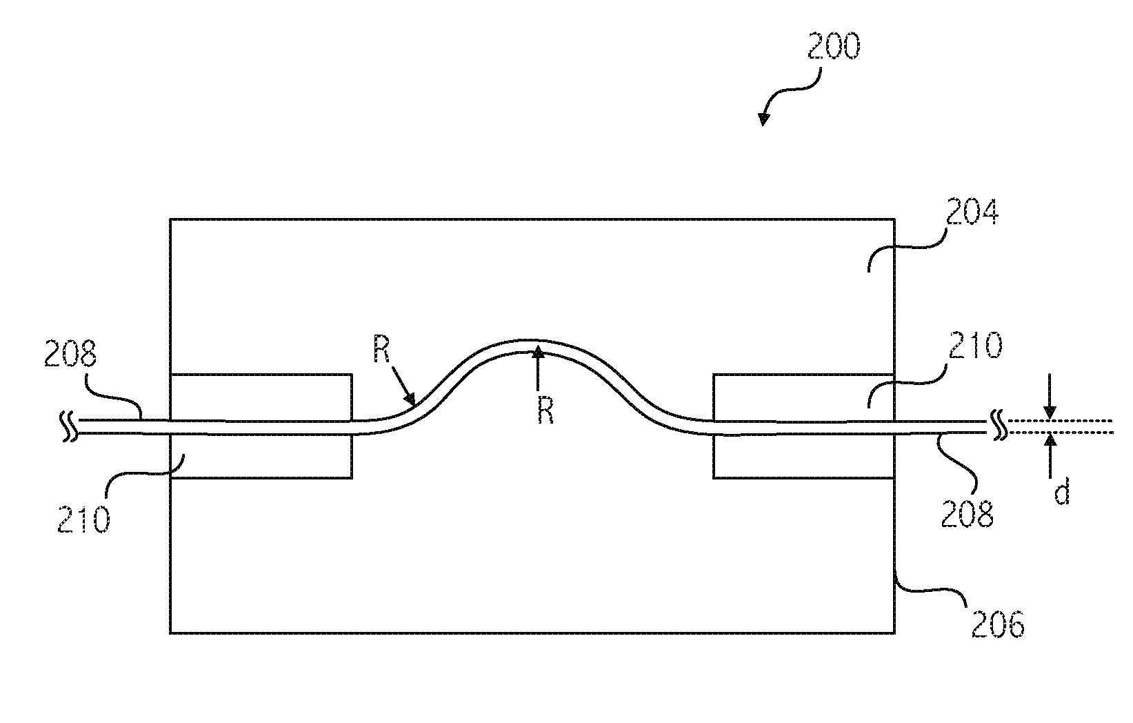
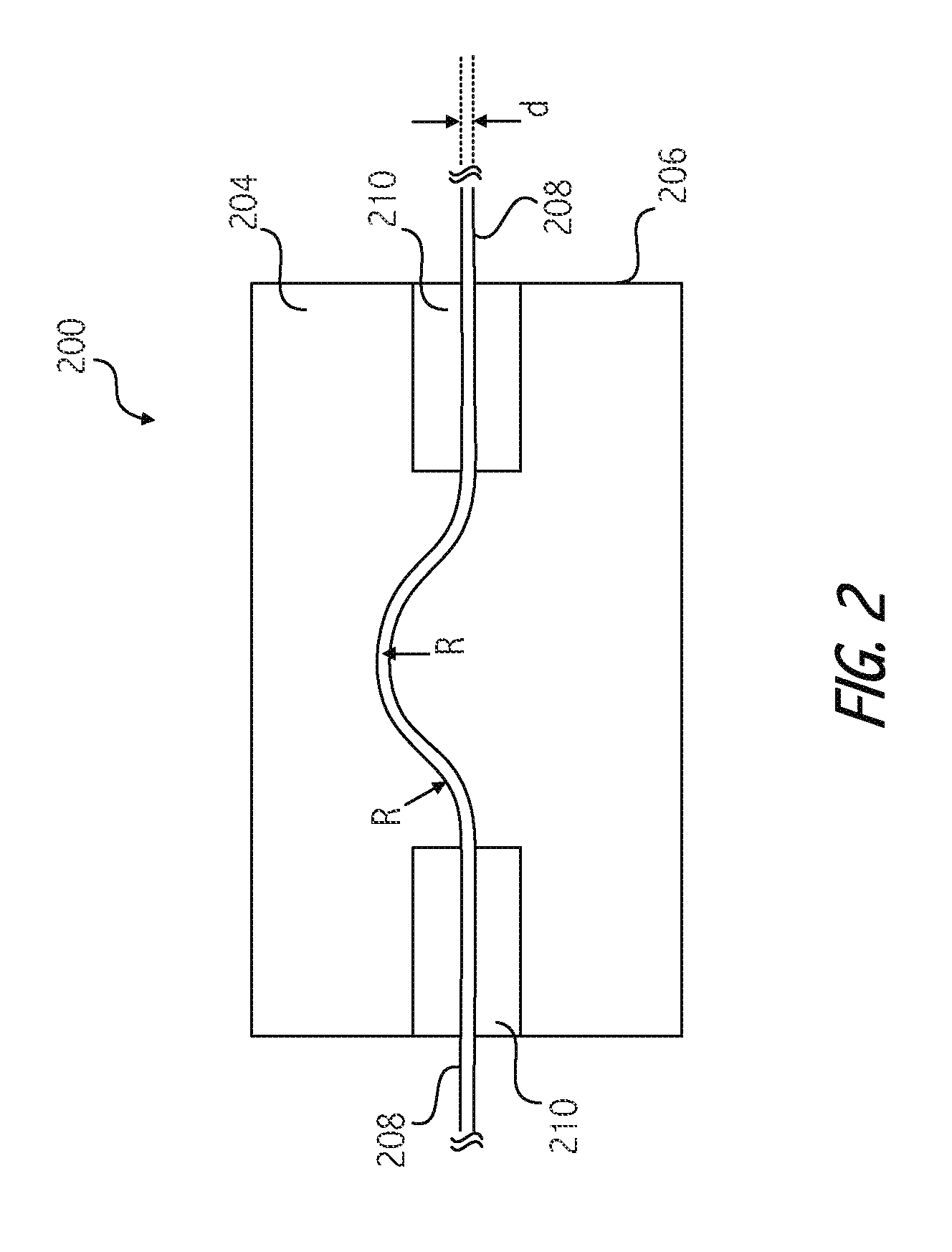
[0038]With reference to FIG. 2, a cleaning device 200 includes complementary contoured cleaning pads 204 and 206 positioned to frictionally engage at least a portion of an elongated emitter electrode 208. In some implementations, cleaning device 200 is moveable to cause cleaning pads 204 and 206 to travel along a longitudinal extent of emitter electrode 208 to thereby remove detrimental material such as silica dendrites, surface contaminants, particulate or other debris from the respective electrode surfaces. Cleaning pads 204 and 206 are contoured to elastically deform electrode 208 in a bend to remove dendrites or other detrimental material from electrode 208 or to otherwise clean or condition the electrode.

[0039]The radius of the bend is selected to avoid plastic deformation of the electrode 208. For example, the electrode diameter and bend radius are selected such that a ratio of the electrode radius to a bend radius does not exceed the yield strain of the electrode material. T...


PUM


Abstract

An apparatus for cleaning an emitter electrode in electrohydrodynamic fluid accelerator and precipitator devices via movement of a cleaning device including complementary contoured cleaning surfaces positioned to frictionally engage and elastically deform the emitter electrode. The opposing cleaning surfaces laterally distort an otherwise linear longitudinal extent of the electrode under tension. The opposing cleaning surfaces are subject to wear, but maintain frictional engagement despite wear depths that exceed a radius of the electrode due at least in part to the at least partially complementary surface contours engaging the electrode under tension. The cleaning device causes respective cleaning surfaces to travel along a longitudinal extent of the emitter electrode to remove detrimental material and optionally to condition the electrode to at least partially mitigate ozone, erosion, corrosion, oxidation, or dendrite formation on the electrode.

Description

BACKGROUND[0001]1. Field of the Invention[0002]This application relates generally to cleaning of electrodes in electrohydrodynamic or electrostatic devices such as electrohydrodynamic fluid accelerators and electrostatic precipitators.[0003]Many electronic devices and mechanically operated devices require air flow to help cool certain operating systems by convection. Cooling helps prevent device overheating and improves long term reliability. It is known to provide cooling air flow with the use of fans or other similar moving mechanical devices; however, such devices generally have limited operating lifetimes, produce noise or vibration, consume power or suffer from other design problems.[0004]The use of an ion flow air mover device, such as an electrohydrodynamic (EHD) device or electro-fluid dynamic (EFD) device, may result in improved cooling efficiency, reduced vibrations, power consumption, electronic device temperatures, and noise generation. This may reduce overall device lif...

Claims


Application Information

Patent Timeline
Patent Type & Authority Applications(United States)
IPC IPC(8): B08B1/00
CPCB03C3/41B03C3/743B03C2201/14B08B1/008B03C2201/04B08B1/30
Inventor BRAUNSTEIN, DANIELBATES, PETERGAO, GUILIANGOLDMAN, RONKNEEN, ELIZABETHSCHWIEBERT, MATTTRAINA, ZACH
Owner TESSERA INC
Learn More