Knuckle Formed Through The Use Of Improved External and Internal Sand Cores and Method of Manufacture

a technology of external and internal sand cores and manufacturing methods, which is applied in the field of rail road couplers, can solve the problems of increased failure risk during use of the knuckle, poor coupling/uncoupling performance of the coupler, and insufficient knuckle thickness, etc., and achieve the effect of reducing micro-shrinkag

Active Publication Date: 2012-01-05
BEDLOE IND LLC
View PDF16 Cites 12 Cited by
  • Summary
  • Abstract
  • Description
  • Claims
  • Application Information

AI Technical Summary

Benefits of technology

[0015]A railcar coupler assembly also is provided that includes a casting having a bearing surface formed at least in part by an external core positioned within a mold. A parting line is formed on at least a portion of the casting

Problems solved by technology

Many knuckles fail from internal and/or external inconsistencies in the metal throughout the thickness of the knuckle.
If one or more cores move during the casting process, then some knuckle walls may end up thinner than others, resulting in offset loading and, in turn, resulting in an increased failure risk during use of the knuckle.
Inconsistent or out of tolerance pulling face contours can result in poor coupling/uncoupling performance of the coupler or in detrimental load paths for the pulling load.
Such sands, however, have several potential drawbacks, which can adversely affect the knuckle's surface finish or its ability to maintain required dimensional control, which in turn can lead to the premature failure of the knuckle and increase maintenance costs as a result of premature failure.
By way of example, when a molten metal is introduced into a mold during casting, it is prone to shrinking as it cools and solidifies.
Shrinkage may lead to the knuckle to form shrinkage defects and even a void in certain portions of the knuckle.
This could cause the coupler to prematurely wear or result in premature fatigue and/or failure.
This may cause damage to the knuckle's surface and cause the knuckle to prematurely fatigue and/or fail.
Moreover, risers and/or large ingates, i.e., material that connects the risers to the casting, are limited in their ability to provide

Method used


Image

  • Knuckle Formed Through The Use Of Improved External and Internal Sand Cores and Method of Manufacture
  • Knuckle Formed Through The Use Of Improved External and Internal Sand Cores and Method of Manufacture
  • Knuckle Formed Through The Use Of Improved External and Internal Sand Cores and Method of Manufacture

Examples


Embodiment Construction

[0029]In some cases, well known structures, materials, or operations are not shown or described in detail. Furthermore, the described features, structures, or characteristics may be combined in any suitable manner in one or more embodiments. It will also be readily understood that the components of the embodiments as generally described and illustrated in the Figures herein could be arranged and designed in a wide variety of different configurations.

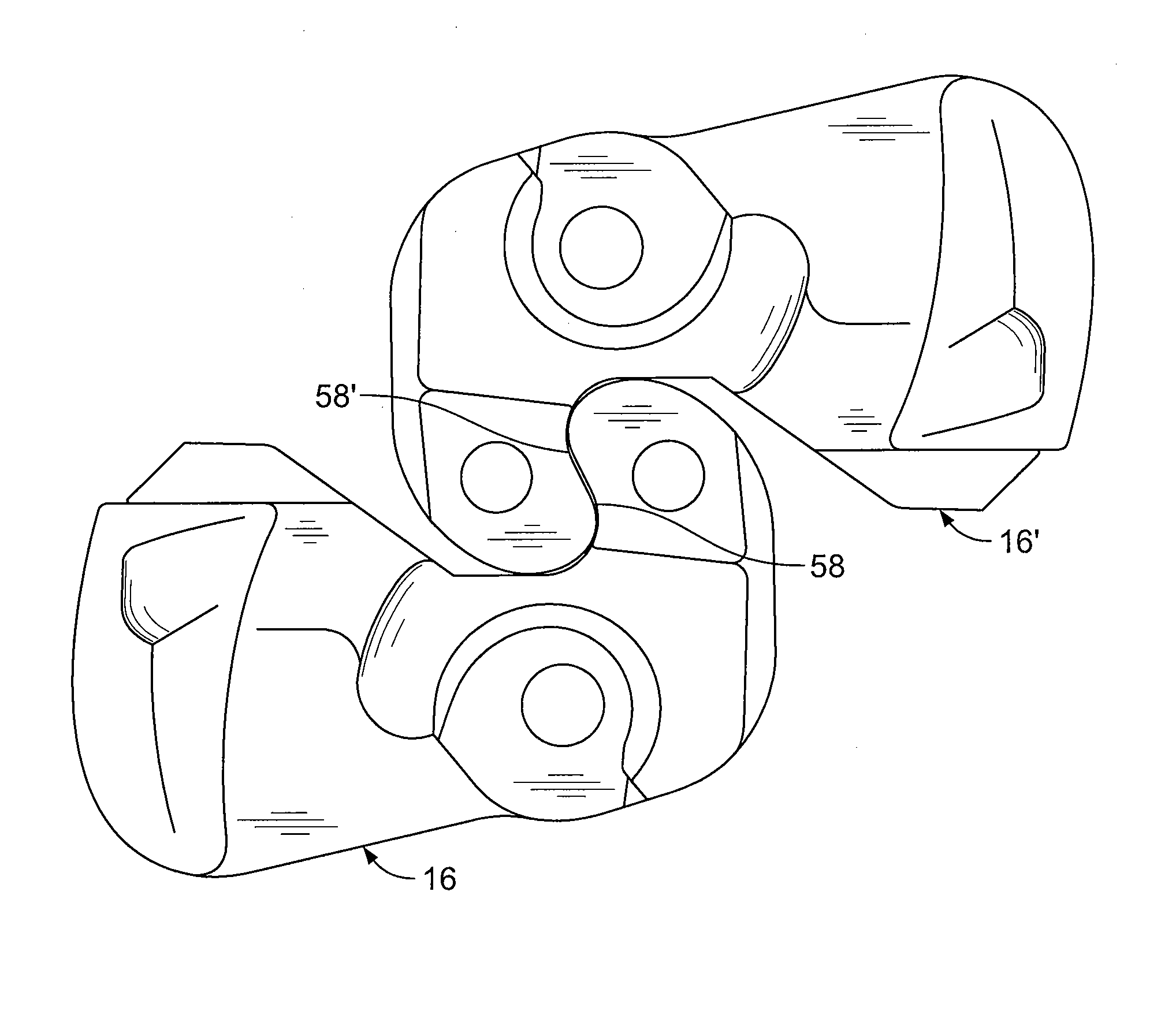
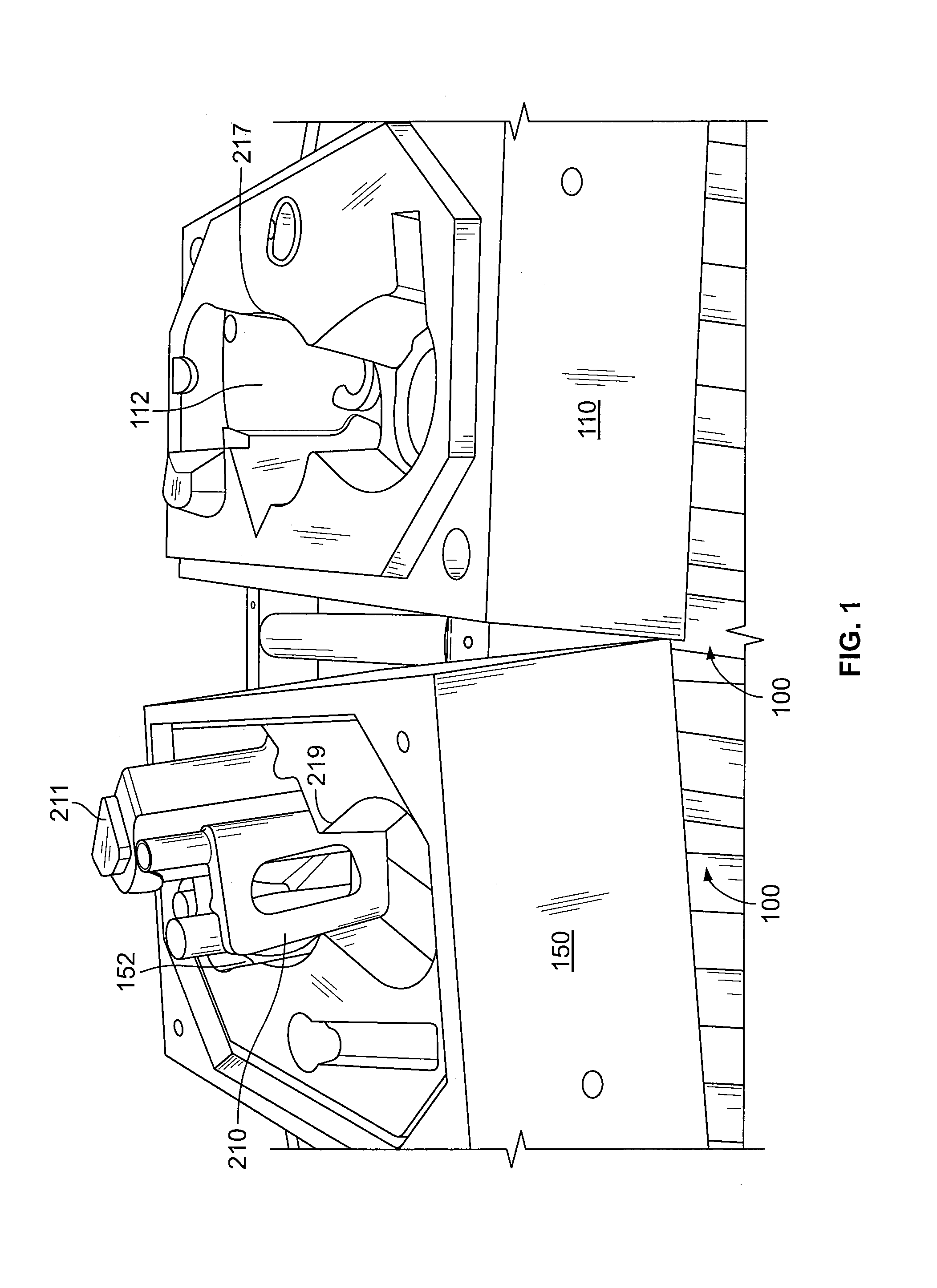
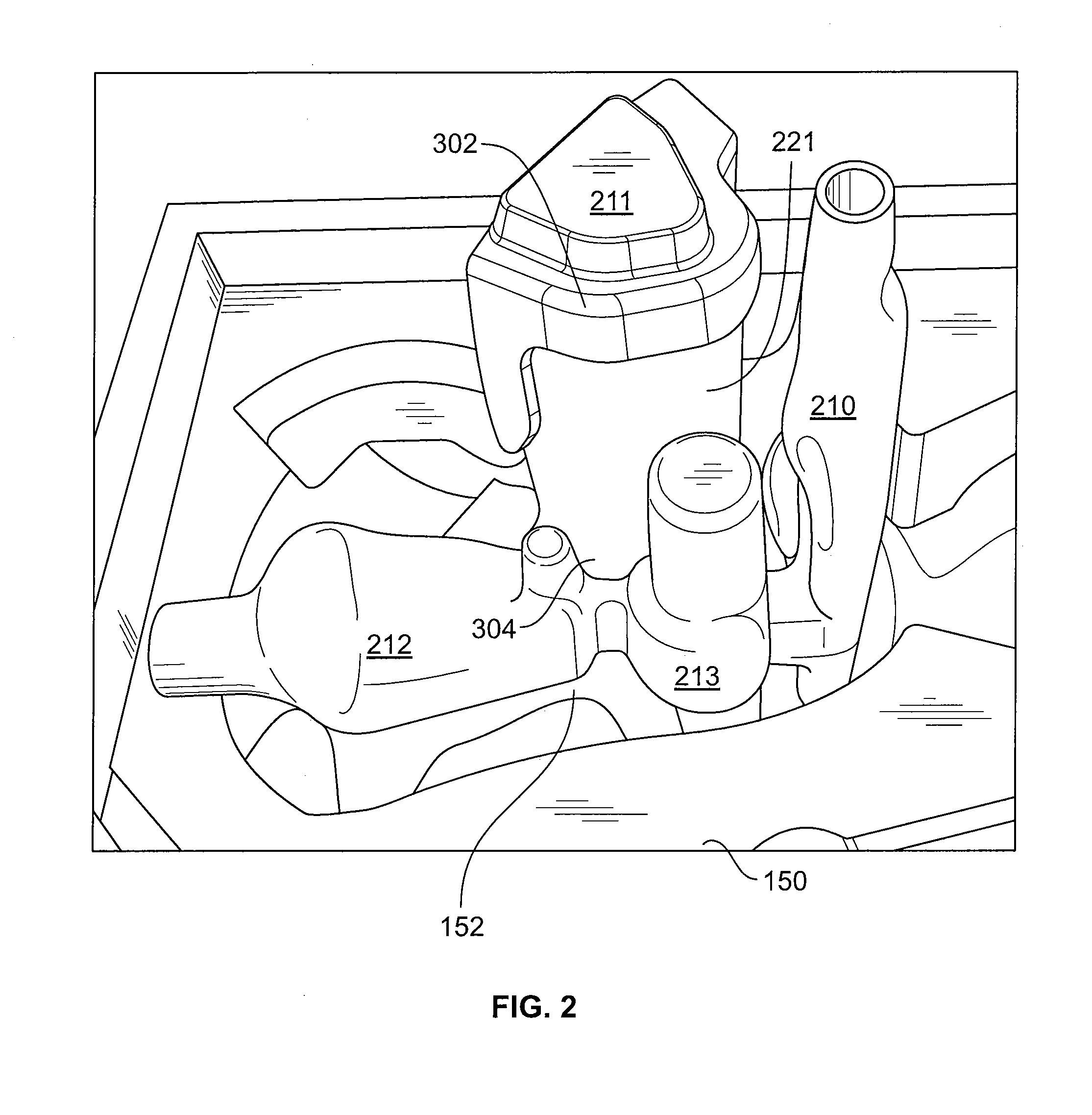
[0030]The disclosure herein describes improved cores to improve the strength, fatigue life, and operational performance of the coupler knuckle. Referring to FIGS. 1 and 2, a railroad coupler knuckle is made from a mold 100 that includes cope and drag sections 110, 150, respectively. The cope and drag sections each include cavities 112, 152, respectively, into which a molten metal or alloy is poured to cast the coupler knuckle. Disposed within the drag section cavity 152 is a plurality of cores. This exemplary embodiment includes a finger...


PUM

PropertyMeasurementUnit
Densityaaaaaaaaaa
Areaaaaaaaaaaa
Metallic bondaaaaaaaaaa

Abstract

A method for manufacturing a railcar coupler knuckle, said method includes providing a cope mold portion and a drag mold portion. The cope and drag mold portions have internal walls that define at least in part perimeter boundaries of a coupler knuckle mold cavity. At least one chill core is positioned within one of the cope mold portion and the drag mold portion. The cope and drag mold portions are closed, with the at least one core therebetween, and the closed cope and drag mold portions and the chill core define a parting line. The mold cavity is filled with a molten metal, which solidifies after filling to form a casting. The casting includes a pulling face portion defined by the chill core, and a central section of the pulling face portion does not contain the parting line and requires no finish grinding upon its formation.

Description

RELATED APPLICATIONS[0001]The present patent document claims the benefit of the filing date under 35 U.S.C. §119(e) of Provisional U.S. Patent Application Ser. No. 61 / 291,584, filed Dec. 31, 2009, which is hereby incorporated by reference.BACKGROUND[0002]1. Technical Field[0003]The present embodiments relate generally to the field of railroad couplers, and more specifically, to the manufacture of an improved knuckle through the use of an improved sand core.[0004]2. Related Art[0005]Railcar couplers are disposed at each end of a railway car to enable joining one end of such railway car to an adjacently disposed end of another railway car. The engageable portion of each of these couplers is known in the railway art as a knuckle.[0006]Typically, a knuckle is manufactured by a mold and several cores that are disposed within the mold. The mold shapes the outside of a casting. The cores are disposed to shape the inside or outside of a casting. Without the inside cores, the casting would b...

Claims


Application Information

Patent Timeline
IPC IPC(8): B61G7/00B22D25/02
CPCB22C9/02B61G3/04B22D15/00B22C9/108
Inventor SMITH, DOUGLASNIBOUAR, F. ANDREWSMERECKY, JERRY R.
Owner BEDLOE IND LLC
Why Eureka
Try Eureka