Magnifying Observation Apparatus

Inactive Publication Date: 2012-01-05
KEYENCE
View PDF25 Cites 27 Cited by
  • Summary
  • Abstract
  • Description
  • Claims
  • Application Information

AI Technical Summary

Benefits of technology

[0038]According to still another embodiment of the invention, in the magnifying observation apparatus, an overlapping rotating range where a rotatable range of the optical imaging device and a rotatable range of the electron beam imaging device overlap each other may range from 60° to 180°. With this configuration, the range where the observation image can be obtained at the same observation angle can widely be secured in each observation device to enhance a degree of freedom of the observation.
[0039]According to still another embodiment of the invention, in the magnifying observation apparatus, the electron beam imaging device may include an electrostatic type or magnetic field type electron lens. With this configuration, the type of the electron beam imaging device can properly be selected according to the purpose and the application. For example, the use of the electrostatic type electron lens can achieve weight reduction, and therefore the observation device can stably be rotated to improve

Problems solved by technology

As described above, in the conventional observation apparatus, there is a problem in that it is not easy to obtain the images having

Method used


Image

  • Magnifying Observation Apparatus
  • Magnifying Observation Apparatus
  • Magnifying Observation Apparatus

Examples


second embodiment

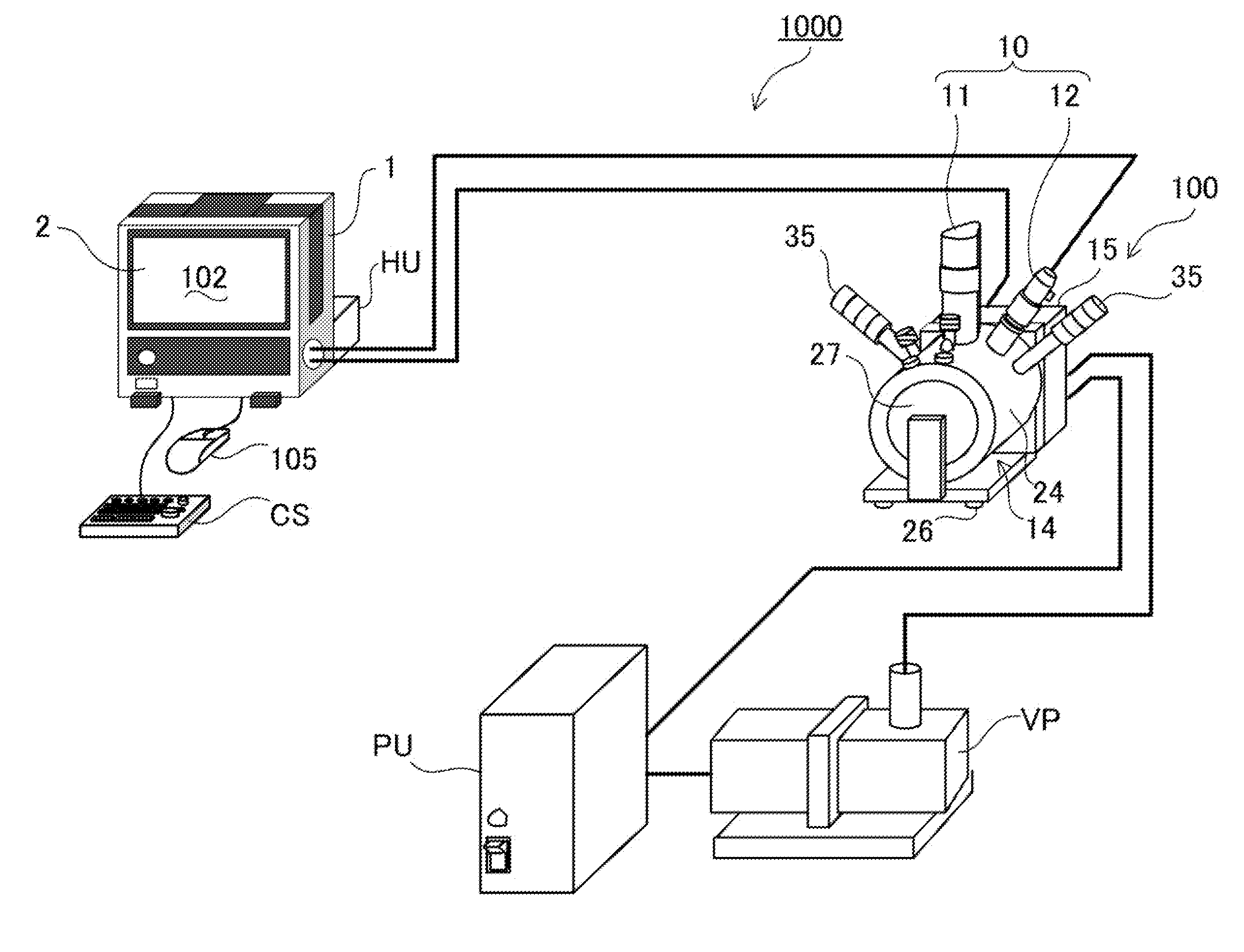
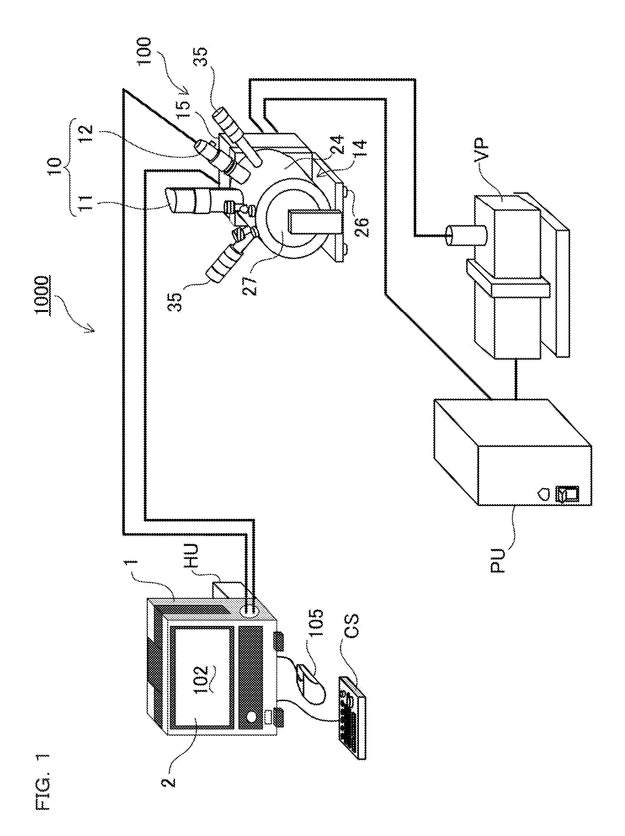
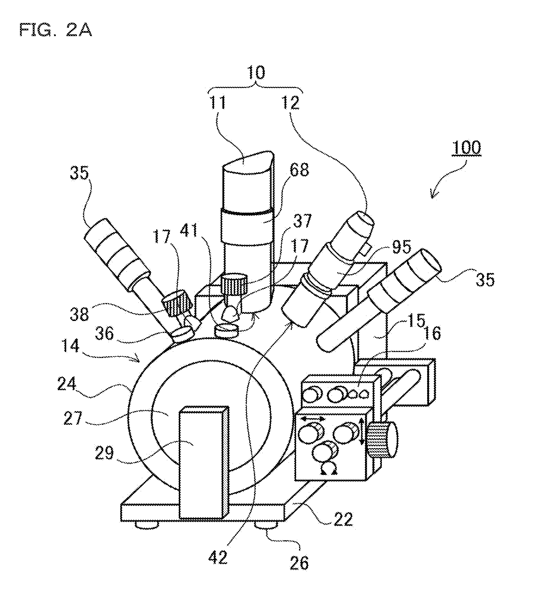
[0214]In the above example, the optical imaging device 12 and the electron beam imaging device 11 are combined by way of example. The present invention can be applied to not only the configuration in which the optical imaging device 12 and the electron beam imaging device 11 are combined but also the configuration in which the optical imaging device 12 and the electron beam imaging device 11 are added if needed. For example, as described above, the magnifying observation system illustrated in the block diagram in FIG. 18 can be configured by detachably mounting the optical imaging device 12 on the magnifying observation system with the mount 39 interposed therebetween. Thus, the optical imaging device 12 can be added if needed while the magnifying observation system is used as the electron microscope. Therefore, the useful magnifying observation system having excellent flexibility and extendibility in which options can be added and removed according to the observation application ca...


PUM


Abstract

Observation fields of an electron microscope image and an optical magnifying observation image are smoothly switched. A magnifying observation apparatus includes: a pair of end-face plates closes end faces of a body portion; an electron beam imaging device mounted on a first position of a cylindrical shaped outer surface of the body portion; an optical imaging device mounted on a second position being different from the first position in the outer surface; a rotating device that rotates the both imaging devices along the outer surface such that a distance from each of the both imaging devices to a common rotation axis of the both imaging devices is kept constant and optical axes of the both imaging devices are oriented toward the rotation axis; a specimen stage that is disposed in the chamber, and arranged to a position that is substantially the same to a height of the rotation axis.

Description

CROSS-REFERENCE TO RELATED APPLICATIONS[0001]The present application claims foreign priority based on Japanese Patent Application No. 2010-152534, filed Jul. 2, 2010, the contents of which is incorporated herein by reference.BACKGROUND OF THE INVENTION[0002]1. Field of the Invention[0003]The present invention relates to a magnifying observation apparatus in which an optical imaging device that can obtain an optical image with an optical observation device such as an optical microscope is added to an electron microscope such as a Scanning Electron Microscope (SEM).[0004]2. Description of Related Art[0005]For example, a transmission electron microscope and a scanning electron microscope are well known as a charged particle beam apparatus in which a signal obtained by irradiating an observation target specimen with a charged particle beam is detected to obtain an observation image. In the electron microscope, for example, an electron traveling direction is freely deflected and an image...

Claims


Application Information

Patent Timeline
IPC IPC(8): G01N23/00
CPCG02B21/0004G02B21/26H01J37/023H01J2237/20235H01J37/226H01J37/228H01J37/28H01J37/16
Inventor KASHIHARA, MITSUHIRO
Owner KEYENCE
Why Eureka
Try Eureka