Induced draft cooling tower
- Summary
- Abstract
- Description
- Claims
- Application Information
AI Technical Summary
Benefits of technology
Problems solved by technology
Method used
Image

Examples
Embodiment Construction
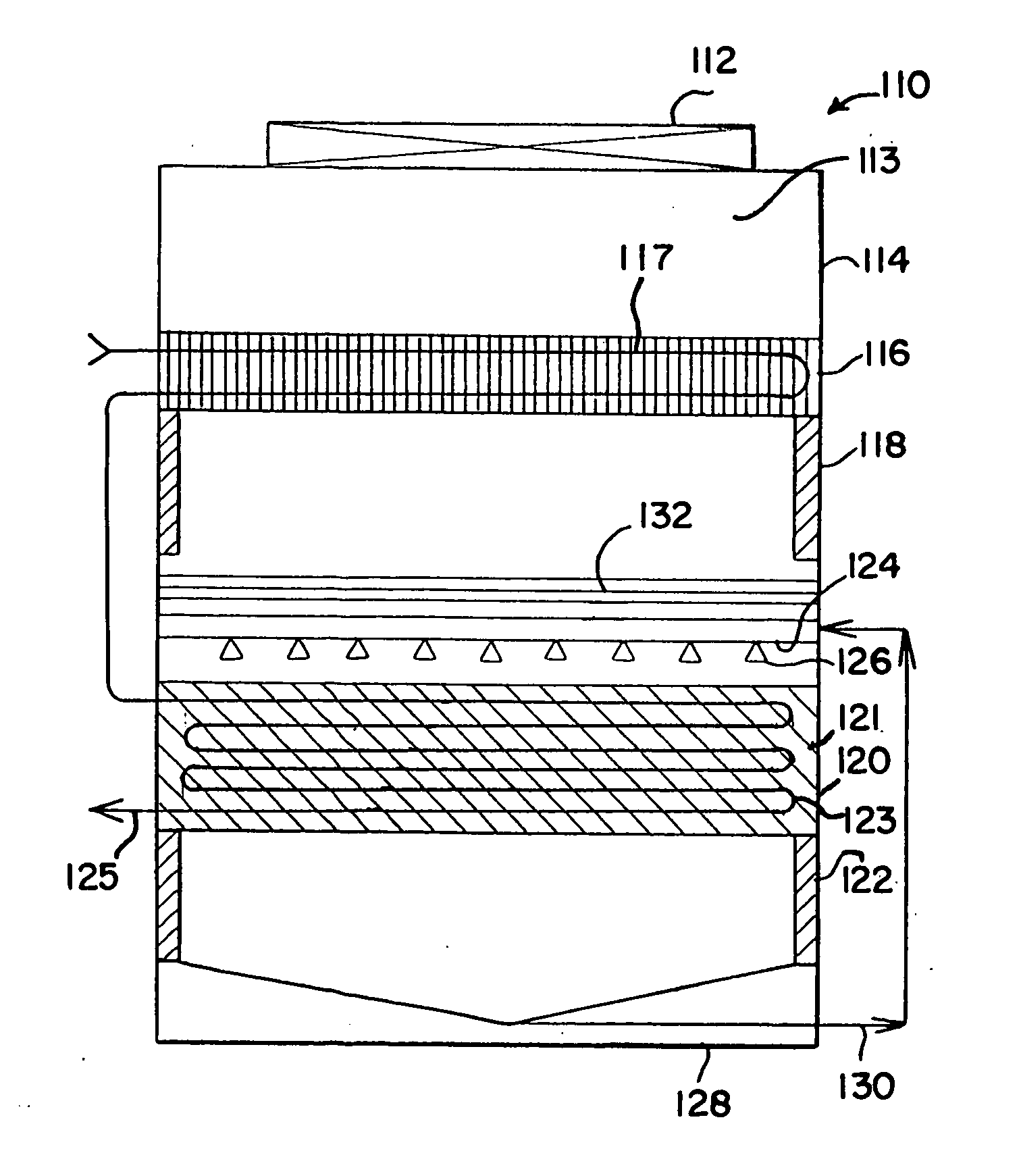
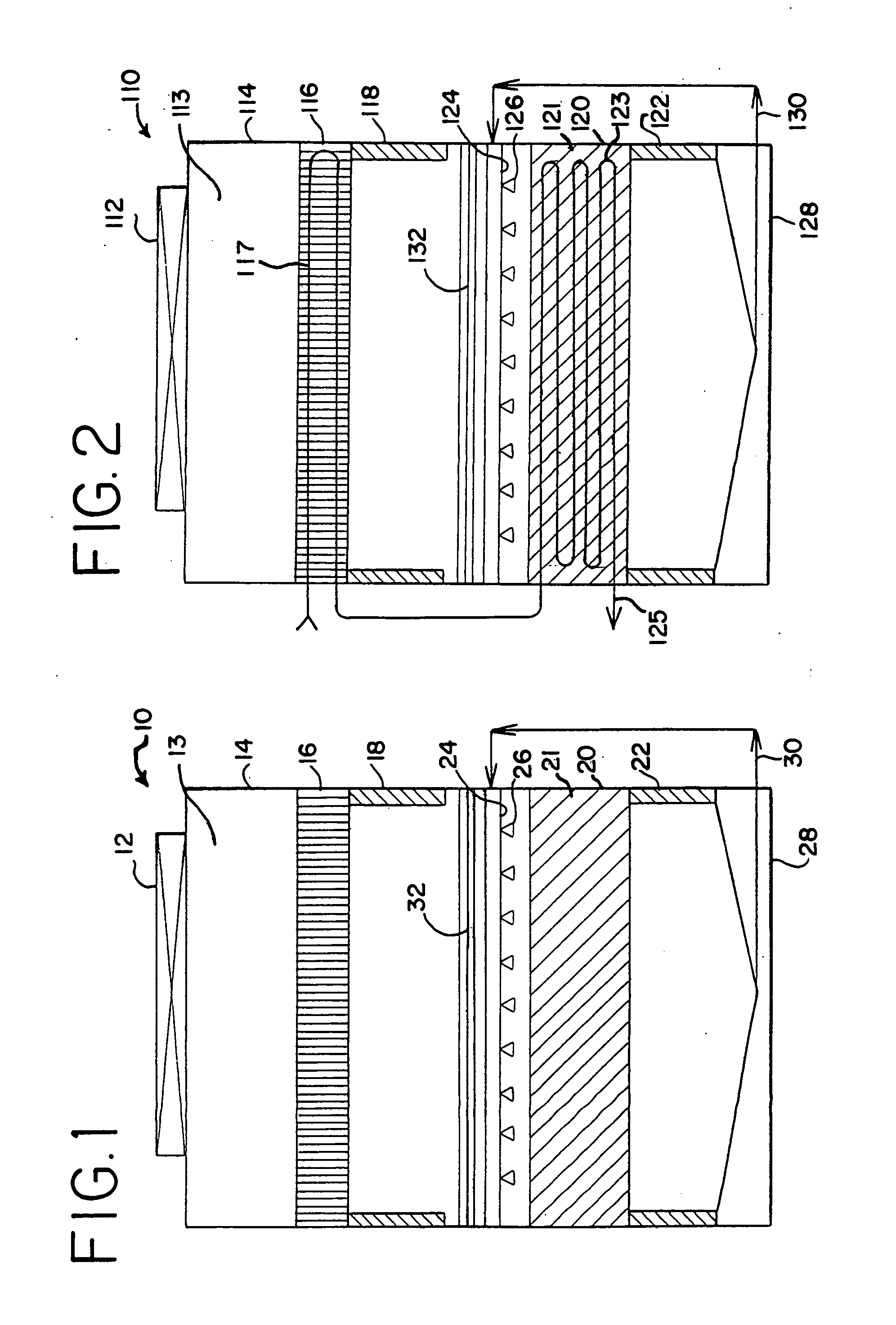
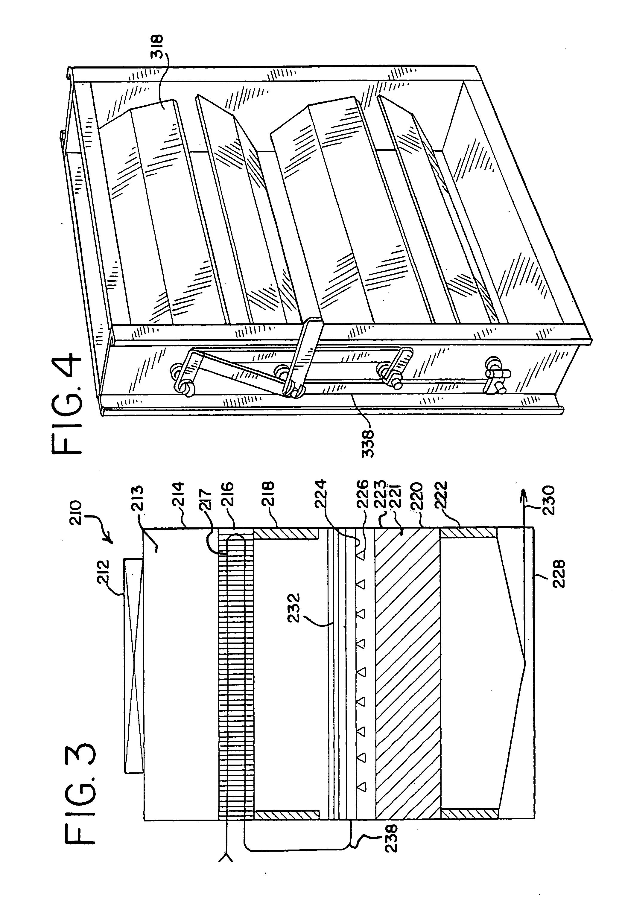
[0013]Referring now to FIG. 1 of the drawings, a cooling tower is shown generally at 10. Such cooling tower is an induced draft tower as fan 12 and fan plenum 13 are generally located at the top of the cooling tower thereby drawing air through inlets 18, 22 located at the sides of the cooling tower. The cooling tower itself is seen to be a generally rectangular structure, usually comprised of galvanized steel or stainless steel structural components. Upper section 14 of cooling tower 10 is seen to comprise a dry sensible cooling coil section 16. Modulating louvers 18 are located in the sides of cooling tower 10, thereby allowing the air flow through modulating louvers 18 to be adjusted from basically full air passage to, upon closing of such louvers, no air passage.
[0014]Lower section 20 of cooling tower 10 is seen to comprise an evaporative cooling section 21. Such evaporative section typically is comprised of a series of spaced parallel closed circuits or fill sheets, designed to ...
PUM
| Property | Measurement | Unit |
|---|---|---|
| Flow rate | aaaaa | aaaaa |
Abstract
Description
Claims
Application Information
 - R&D
- Intellectual Property
- Life Sciences
- Materials
- Tech Scout
- Unparalleled Data Quality
- Higher Quality Content
- 60% Fewer Hallucinations
Browse by: Latest US Patents, China's latest patents, Technical Efficacy Thesaurus, Application Domain, Technology Topic, Popular Technical Reports.
© 2025 PatSnap. All rights reserved.Legal|Privacy policy|Modern Slavery Act Transparency Statement|Sitemap|About US| Contact US: help@patsnap.com