

Video Feedback Loop
- Summary
- Abstract
- Description
- Claims
- Application Information
AI Technical Summary
Benefits of technology
Problems solved by technology
Method used
Image

Examples
Embodiment Construction
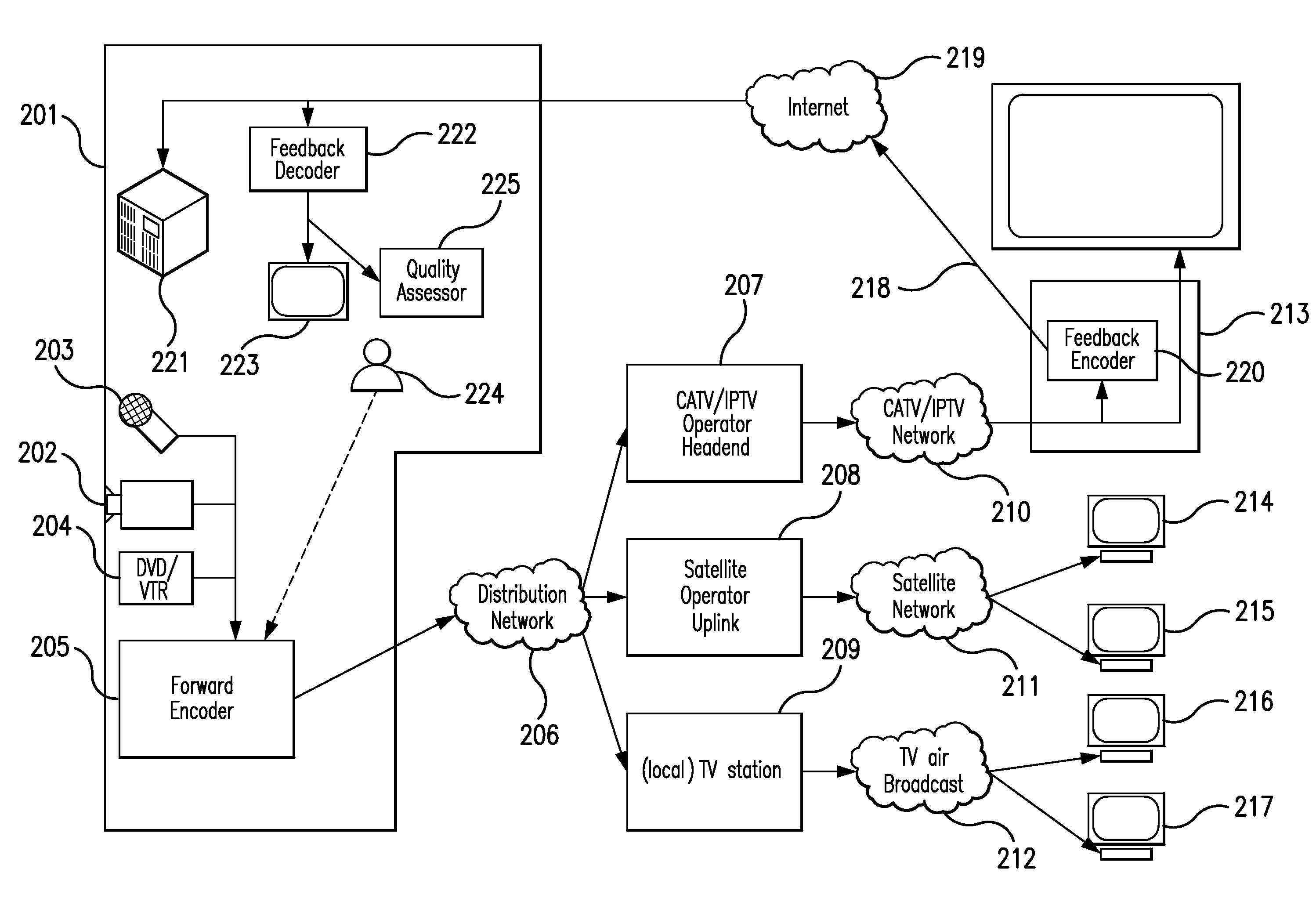
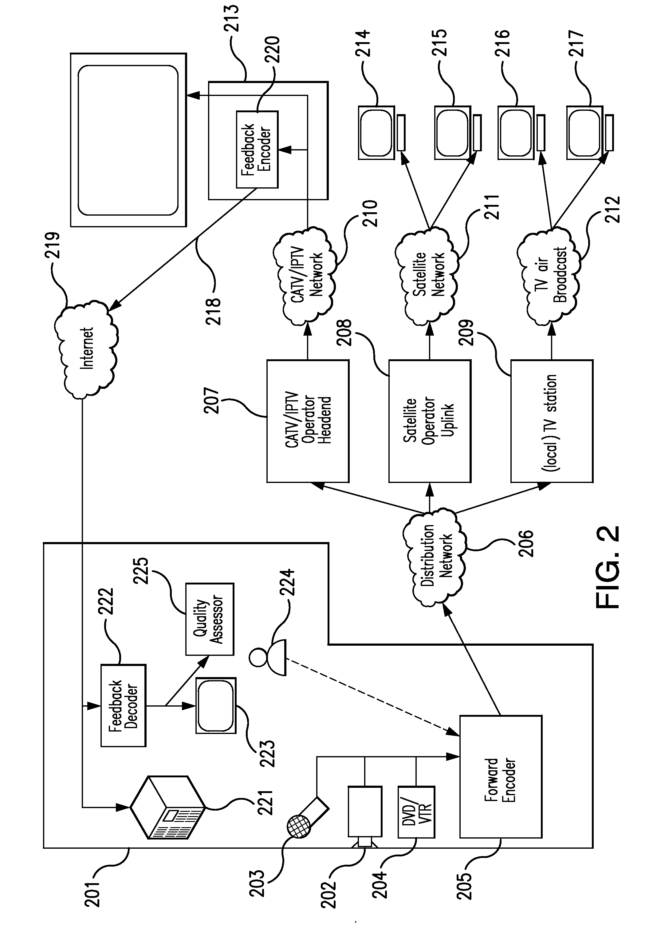
[0036]The present invention discloses techniques to enable, among other applications, the monitoring, quality control, automatic verification of content use, confidence monitoring, and / or net-return monitoring of a forward video transmission between a content factory and distribution or consuming site(s). The distribution or consuming site(s) can return video signals based on the forward video transmission from various handover points back to the originating site to provide information on the video quality at the handover point.
[0037]FIG. 2 illustrates an exemplary setup according to the invention, wherein the feedback originates from a consumer site. A content factory (201) prepares the content. In a live setting, the content can be recorded, for example, by one or more cameras (202) and microphones (203). The content can also be pre-recorded on analog or digital media (204) such as a video tape recorder or a DVD. From any of the aforementioned sources, the content is either alread...
PUM
 Abstract
Description
Claims
Application Information