
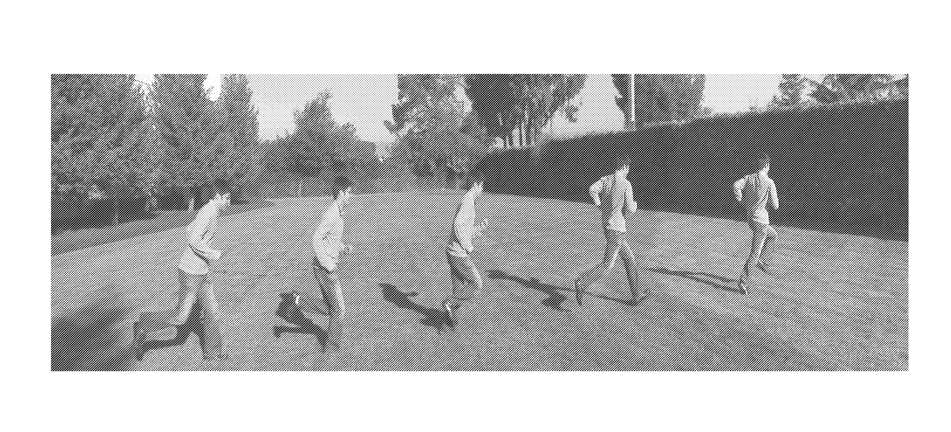
Tail the motion method of generating simulated strobe motion videos and pictures using image cloning

a motion and motion technology, applied in the field of strobe motion video and picture generation, can solve the problems that methods and similar recently developed techniques cannot be applied, and achieve the effects of increasing the cost function within the overlap area, preventing cutting, and increasing the cost function

Inactive Publication Date: 2012-01-05
SONY CORP
View PDF12 Cites 89 Cited by
  • Summary
  • Abstract
  • Description
  • Claims
  • Application Information

AI Technical Summary

Benefits of technology

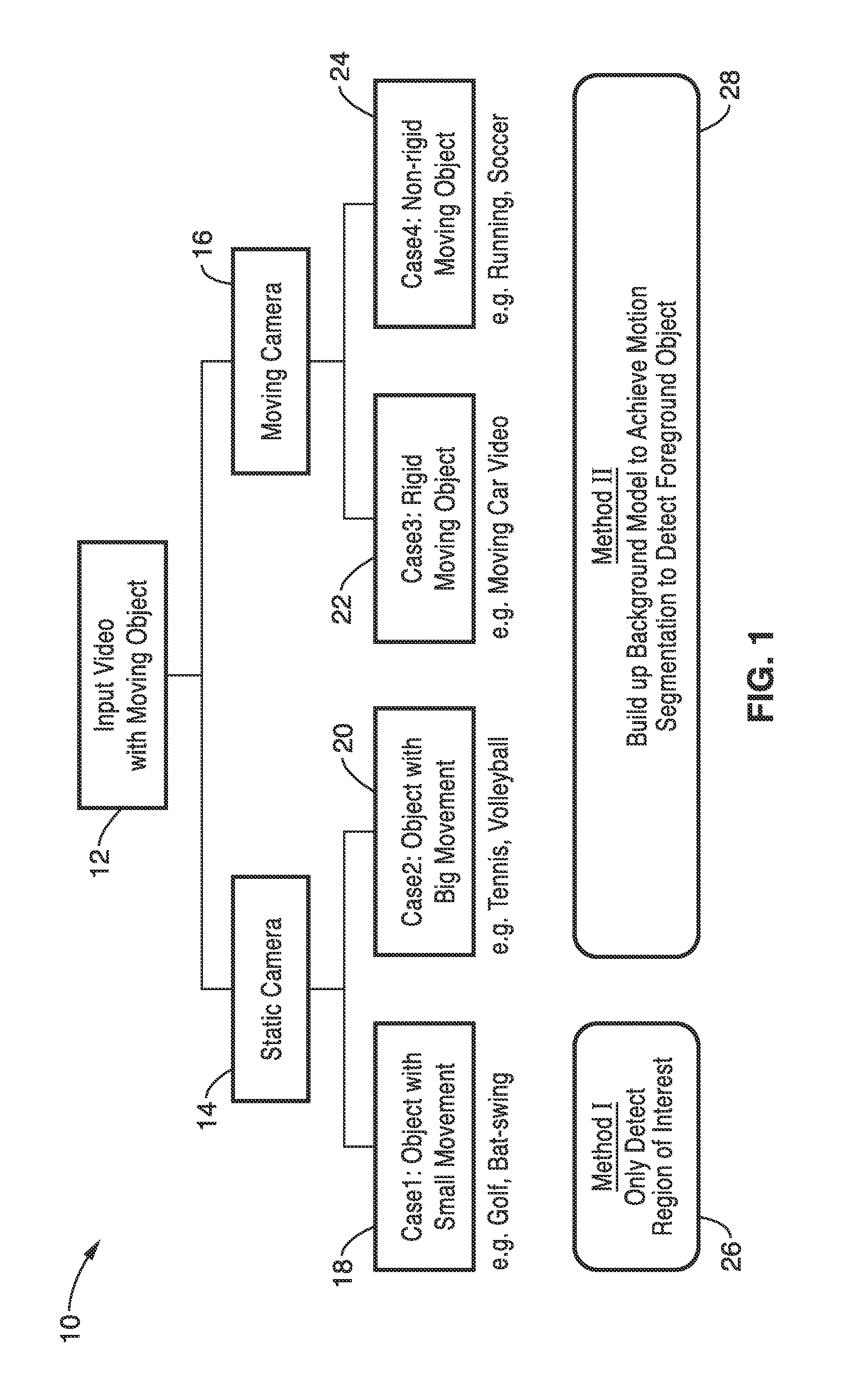
[0012]During processing, programming within the apparatus categorizes moving target objects within the video into multiple categories. Target objects within the different categories are handled in different ways according to the invention. One level of categorization depends on gross (large) movements. It should be appreciated that objects with sufficiently large movements require a moving camera field of view, to capture the movement. Objects subject to lesser motions, can be captured with a static camera (non-moving field of view) having a field of view which is adequate to span the whole range of the target object movement. These primary categories are then preferably sub-divided to enhance operation of the technique.
[0018]In at least one implementation, still image simulated strobe effect output is generated in response to programming executable on the computer, comprising: (a) dividing an image area which overlaps between each pair of adjacent images in response to; (b) forcing a cutting line to pass through a middle point of centroids of an identified moving object in each pair of adjacent images using a cost function; and (c) increasing the cost function within the image area of the identified moving object to prevent cutting through the identified moving object.
[0020]In at least one implementation, image differences are determined as a basis for segmenting a region of interest within the video sequence. In at least one implementation, the simulated strobe motion output contains multiple foreground images of the target object, representing different time periods along a trajectory captured in the received video sequence, over a single background image. In at least one implementation, the still image simulated strobe output is generated in response to programming executable on the computer, comprising: (a) dividing an overlapping area between each pair of adjacent images in response to; (b) forcing a cutting line to pass through a middle point of centroids of the target object, as represented in the adjacent images, using a cost function; and (c) increasing the cost function within the overlapping area, between the pair of adjacent images, to prevent cutting through representations of the target object in either of the pair of adjacent images.

Problems solved by technology

However, this method, and similar recently developed techniques, can be only applied when the target object is subject to relatively large motions.

Method used


Image

  • Tail the motion method of generating simulated strobe motion videos and pictures using image cloning
  • Tail the motion method of generating simulated strobe motion videos and pictures using image cloning
  • Tail the motion method of generating simulated strobe motion videos and pictures using image cloning

Examples


embodiment 1

[0102]2. The apparatus of embodiment 1, wherein said programming executable on said computer for generating a simulated strobe effect output comprises: applying motion segmentation to detect a foreground object in each image frame of the received video sequence; selecting at least one checkpoint image based on time differences of each image frame within the received video sequence to attain a desired interval between checkpoint images; and updating an overall foreground mask and pasting an overall foreground area on future images as each said checkpoint image is reached.

embodiment 2

[0103]3. The apparatus of embodiment 2, further comprising programming executable on said computer for generating a background model for applying said motion segmentation if the relative motion of the target object is large in relation to the frame size.

[0104]4. The apparatus of embodiment 1, further comprising programming executable on said computer for selecting between motion tracking for large motions or image differencing for small motion when determining a region of interest (ROI) within the received video sequence.

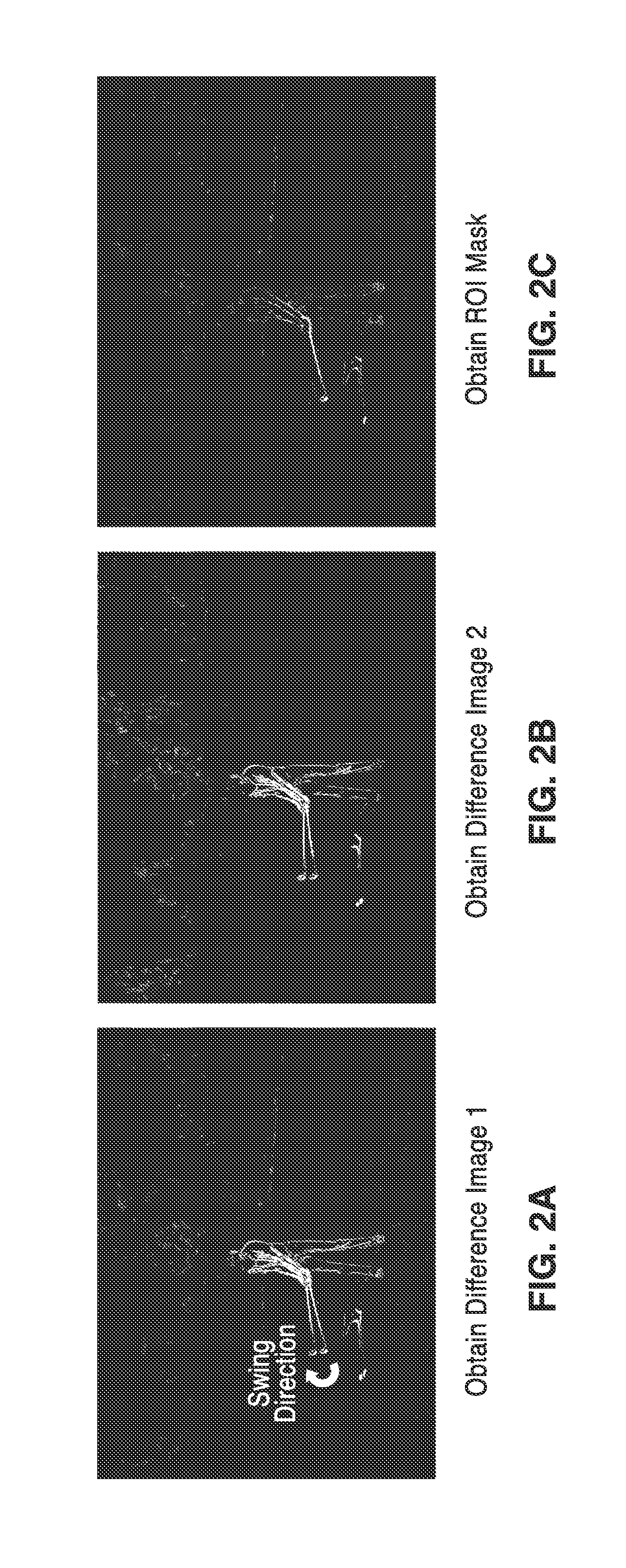
[0105]5. The apparatus of embodiment 1, further comprising programming executable on said computer for determining image differenced as a basis of segmenting the region of interest within the received video sequence.

[0106]6. The apparatus of embodiment 1, wherein said multiple strobe effect generation process comprises a first process and a second process within programming executable on said computer; wherein said first process is selected in response to detection ...

embodiment 12

[0113]13. The apparatus of embodiment 12, further comprising programming executable on said computer for determining image difference as a basis for segmenting a region of interest within the video sequence

[0114]14. The apparatus of embodiment 12, wherein said simulated strobe motion output contains multiple foreground images of the target object, representing different time periods along a trajectory captured in the received video sequence, over a single background image.

[0115]15. The apparatus of embodiment 12, wherein said apparatus is selected from a group of devices configured for processing received video consisting of camcorders, digital cameras, video recorders, image processing applications, televisions, display systems, computer software, video / image editing software, and / or combinations thereof.

[0116]16. The apparatus of embodiment 12, wherein said simulated strobe effect output comprises a video.

[0117]17. The apparatus of embodiment 12, wherein said simulated strobe effe...


PUM


Abstract

The apparatus generates simulated strobe effects in the form of video or still image output in response to receipt of a video stream, and without the need of additional strobe hardware. Videos of a moving target object are categorized into one of multiple categories, from which a strobe generation process is selected. In one mode, the two categories comprise target objects with either small motion or large motions in relation to the frame size. Interoperation between image registration and cloning are utilized to produce simulated strobe motion videos or pictures. Motion segmentation is applied to the foreground object in each image frame, and a foreground mask is updated as each checkpoint is reached along the object trajectory, such as in response to time differences between checkpoints. Potential applications include special features for camcorders, digital cameras, or computer software.

Description

CROSS-REFERENCE TO RELATED APPLICATIONS[0001]Not ApplicableSTATEMENT REGARDING FEDERALLY SPONSORED RESEARCH OR DEVELOPMENT[0002]Not ApplicableINCORPORATION-BY-REFERENCE OF MATERIAL SUBMITTED ON A COMPACT DISC[0003]Not ApplicableNOTICE OF MATERIAL SUBJECT TO COPYRIGHT PROTECTION[0004]A portion of the material in this patent document is subject to copyright protection under the copyright laws of the United States and of other countries. The owner of the copyright rights has no objection to the facsimile reproduction by anyone of the patent document or the patent disclosure, as it appears in the United States Patent and Trademark Office publicly available file or records, but otherwise reserves all copyright rights whatsoever. The copyright owner does not hereby waive any of its rights to have this patent document maintained in secrecy, including without limitation its rights pursuant to 37 C.F.R. §1.14.BACKGROUND OF THE INVENTION[0005]1. Field of the Invention[0006]This invention pert...

Claims


Application Information

Patent Timeline
Patent Type & Authority Applications(United States)
IPC IPC(8): H04N9/74
CPCH04N5/2625H04N5/144
Inventor HUANG, KUANG-MANROBERTSON, MARKLIU, MING-CHANG
Owner SONY CORP
Learn More