Laminate optical body, optical film, liquid crystal display apparatus using said optical film, and method for producing laminate optical body

a technology of laminate optical body and retardation film, which is applied in the direction of instruments, other domestic articles, synthetic resin layered products, etc., can solve the problems of large number of problems, difficult to realize optical properties that can be put into practical use, and difficult to express the slow axis of retardation film in the td of raw film, etc., to achieve excellent production efficiency, small display unevenness, and extremely small retardation unevenness of laminate optical body

Inactive Publication Date: 2012-01-05
NITTO DENKO CORP
View PDF5 Cites 23 Cited by
  • Summary
  • Abstract
  • Description
  • Claims
  • Application Information

AI Technical Summary

Benefits of technology

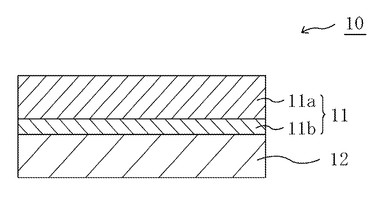
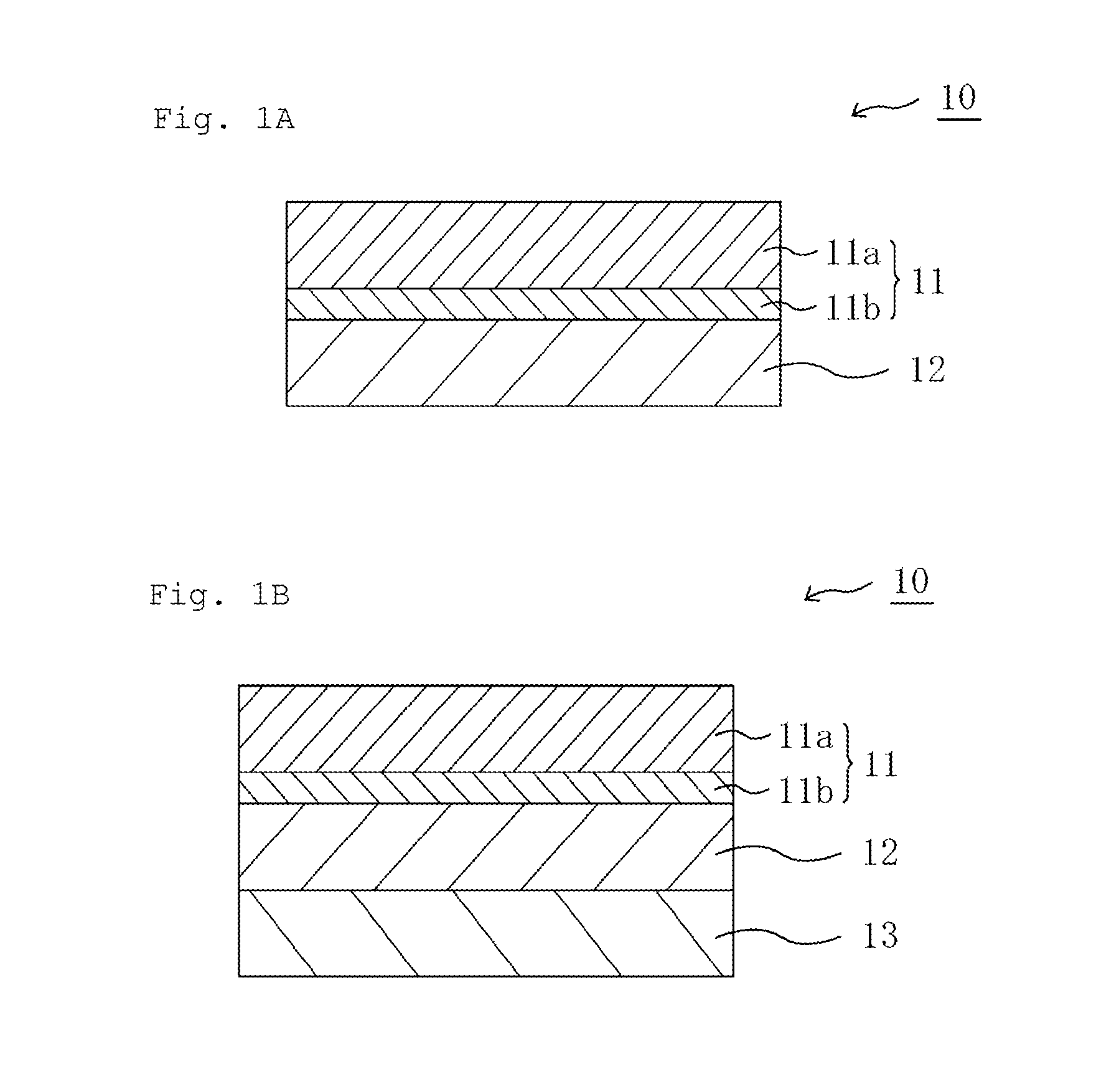
[0021]According to the present invention, an extremely thin polarizing film having an absorption axis in its short direction is used, and hence the film and a retardation film having a slow axis in its lengthwise direction can be laminated by the roll-to-roll process. Therefore, a laminate optical body in which the axis shift of the slow axis of the retardation film is extremely small can be obtained. Further, the dimensions of such extremely thin polarizing film as described above change at so small a rate (particularly under a high-temperature, high-humidity environment) that the distortion of the retardation film resulting from the dimensional change of the polarizing film in the laminate optical body also becomes extremely small. As a result, the retardation unevenness of the laminate optical body becomes extremely small. As a result of synergistic action of the above-mentioned effects, the laminate optical body of the present invention, when incorporated into a liquid crystal display apparatus, can realize a liquid crystal display apparatus showing extremely small display unevenness. In addition, the laminate optical body of the present invention is excellent in production efficiency because the laminate optical body can be produced by the roll-to-roll process.

Problems solved by technology

However, it is difficult to express the slow axis of the retardation film in the TD of the raw film.
Therefore, when a polarizing plate integrated with a retardation plate is to be produced with a conventional polarizing plate (polarizing plate having an absorption axis in the lengthwise direction of a raw film), attachment by the roll-to-roll process involves a large number of problems, and hence there is no choice but to attach plates one by one by punching.
Even if the attachment by the roll-to-roll process is achieved, the shift of the slow axis of the retardation film is so large as described above that it is difficult to realize optical properties that can be put into practical use.
Further, the conventional polarizing plate involves such a problem that its dimensions largely change under a high-temperature, high-humidity environment.
As a result, even the polarizing plate integrated with a retardation plate involves the following problem.
The retardation film distorts owing to the dimensional change of the polarizing plate under a high-temperature, high-humidity environment, and hence retardation unevenness occurs.
When a conventional polarizing plate integrated with a retardation plate (laminate of a polarizing plate having an absorption axis in its MD and a retardation film having a slow axis in its TD) is mounted on a liquid crystal display apparatus, the following problem arises as a result of the above-mentioned problem.
Display unevenness or brightness unevenness occurs.
Further, even when a specific retardation film is used, a problem arises in addition to such problem as described above common to polarizing plates integrated with retardation plates.
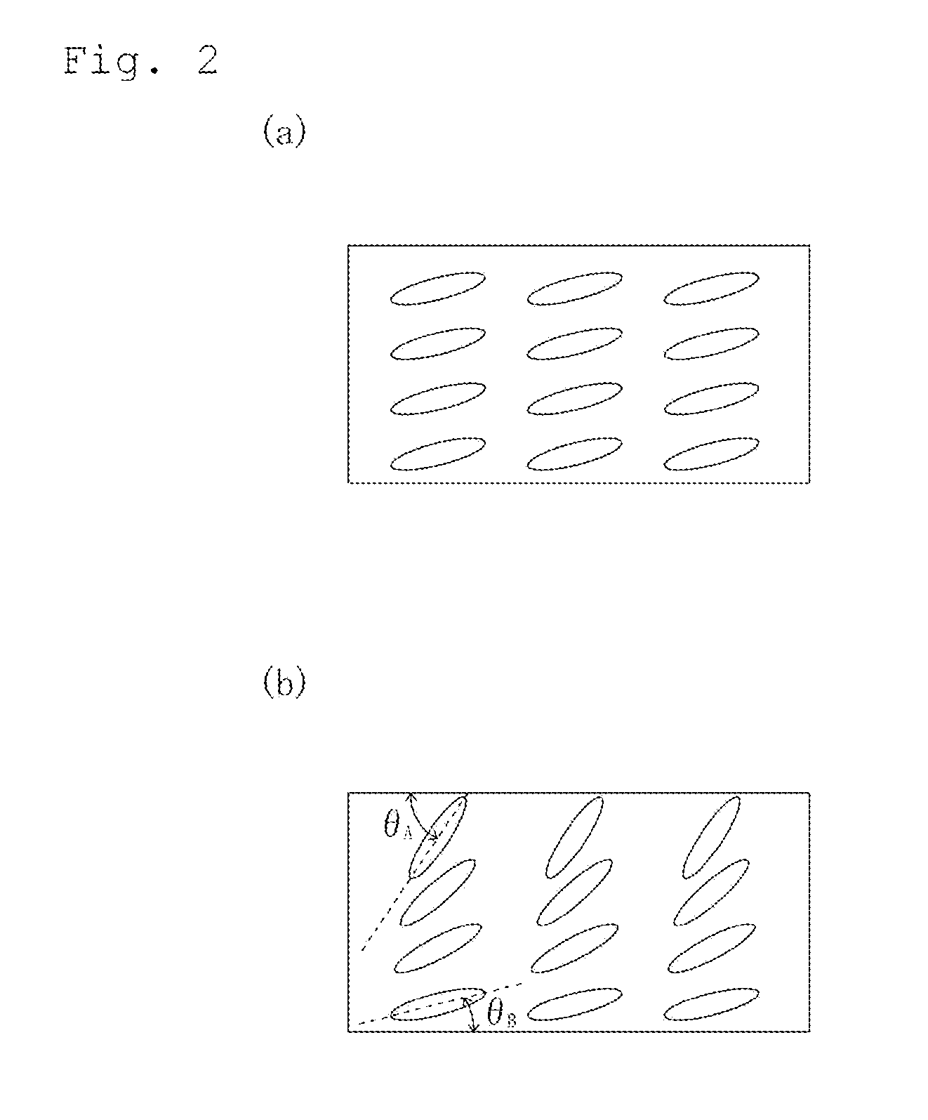
However, it is extremely difficult to clarify the direction of the tilt alignment of the O plate at the time of the production of the laminate, and hence a method involving attaching plates one by one involves problems such as a reduction in production efficiently resulting from the operation of observing the direction of the tilt alignment and a reduction in yield due to false attachment.
It is extremely difficult to accurately express the slow axis of the O plate in the TD of the raw film as in the case of any other retardation film.
As a result, it may become difficult to realize desired optical compensation.

Method used


Image

  • Laminate optical body, optical film, liquid crystal display apparatus using said optical film, and method for producing laminate optical body
  • Laminate optical body, optical film, liquid crystal display apparatus using said optical film, and method for producing laminate optical body
  • Laminate optical body, optical film, liquid crystal display apparatus using said optical film, and method for producing laminate optical body

Examples


reference example 1

(Production of Polarizing Film)

[0175]A polyvinyl alcohol resin (manufactured by The Nippon Synthetic Chemical Industry Co., Ltd., product name: “Gohsenol NH-18,” degree of saponification: 98 to 990) was dissolved in hot water, and then the solution was cooled. Thus, a 7-wt % aqueous solution of polyvinyl alcohol was prepared. Meanwhile, a norbornene-based resin film (manufactured by JSR Corporation, product name: “ARTON,” thickness: 100 μm) was prepared as a base material. The above-mentioned aqueous solution was applied to the surface of the base material, and was then dried at 100° C. for 10 minutes. Thus, a polyvinyl alcohol thin film having a thickness of 7 μm was formed on the base material. A laminate of the base material and the thin film thus obtained was stretched in its short direction at a stretching temperature of 140° C. and a stretching ratio of 4.5 times. The stretched laminate had an entire thickness of 60 μm and the polyvinyl alcohol thin film had a thickness of 3 μ...

reference example 2

(Production of Polarizing Film)

[0176]A polyvinyl alcohol resin (manufactured by The Nippon Synthetic Chemical Industry Co., Ltd., product name: “Gohsenol NH-18,” degree of saponification: 98 to 99%) was dissolved in hot water, and then the solution was cooled. Thus, a 7-wt % aqueous solution of polyvinyl alcohol was prepared. Meanwhile, a norbornene-based resin film (manufactured by JSR Corporation, product name: “ARTON,” thickness: 100 μm) was prepared as a base material. The above-mentioned aqueous solution was applied to the surface of the base material, and was then dried at 100° C. for 10 minutes. Thus, a polyvinyl alcohol thin film having a thickness of 7 μm was formed on the base material. A laminate of the base material and the thin film thus obtained was stretched in its short direction at a stretching temperature of 140° C. and a stretching ratio of 4.5 times. The stretched laminate had an entire thickness of 60 μm and the polyvinyl alcohol thin film had a thickness of 3 μ...

reference example 3

(Polarizing Plate)

[0177]A commercially available polarizing plate (manufactured by Nitto Denko Corporation, product name: “NPF-TEG1465DU”) having a construction “protective film / polarizer / protective film” was used. The in-plane retardation of the protective film on a liquid crystal cell side of the polarizing plate is substantially zero. 3n addition, the polarizing plate has a single axis transmittance of about 44%, and has an absorption axis in its lengthwise direction (MD).


PUM

PropertyMeasurementUnit
thicknessaaaaaaaaaa
tilt angleaaaaaaaaaa
thickness direction retardationaaaaaaaaaa

Abstract

The present invention provides a laminate optical body, which is excellent in production efficiency, shows an extremely small axis shift and can realize a liquid crystal display apparatus showing small display unevenness. The laminate optical body of the present invention includes an elongated polarizing film having an absorption axis in a short direction thereof, and including a base material layer and a hydrophilic polymer layer to which a dichromatic substance adsorbs; and an elongated retardation film having a slow axis in a lengthwise direction thereof. The polarizing film is a laminate including the base material layer and the hydrophilic polymer layer to which a dichromatic substance adsorbs. The laminate optical body is elongated. Preferably, the hydrophilic polymer layer has a thickness of 1 μm to 10 μm.

Description

TECHNICAL FIELD[0001]The present invention relates to a laminate optical body, an optical film and a liquid crystal display apparatus using the optical film, and a method of producing a laminate optical body.BACKGROUND ART[0002]A liquid crystal display apparatus includes a polarizing plate as an essential component as a result of its display mechanism. A product obtained by causing a polyvinyl alcohol (PVA)-based film to adsorb a dichromatic substance and uniaxially stretching the resultant has been widely used as the polarizing plate. The absorption axis of such polarizing plate is expressed in a lengthwise direction because the polarizing plate is produced by stretching an elongated PVA-based film in the lengthwise direction.[0003]By the way, in order that the retardation of a liquid crystal cell in a liquid crystal display apparatus may be optically compensated, in many cases, a predetermined retardation film must be provided so that its slow axis may be perpendicular to the abso...

Claims


Application Information

Patent Timeline
Patent Type & Authority Applications(United States)
IPC IPC(8): C09K19/00B32B9/04B29D11/00B32B3/00
CPCB32B27/08G02B5/3016Y10T428/10G02F1/133634Y10T428/265G02B5/3033B32B27/281B32B27/288B32B27/306B32B27/34B32B27/36B32B2307/412B32B2307/418B32B2307/42B32B2307/516B32B2307/728B32B2307/732B32B2457/202C09K2323/00Y10T428/31504
Inventor NISHIMURA, AKINORIYAGINUMA, HIRONORIYOSHIMI, HIROYUKITAKEDA, KENTAROUINAGAKI, JUNICHIKINOSHITA, RYOJIKITAGAWA, TAKEHARU
Owner NITTO DENKO CORP
Why Eureka
Try Eureka