Nail-plated composite structural system

Inactive Publication Date: 2012-01-05
WONG CHIANG HENG
View PDF11 Cites 28 Cited by
  • Summary
  • Abstract
  • Description
  • Claims
  • Application Information

AI Technical Summary

Benefits of technology

[0012]The present invention seeks to provide a more economical, practical and effective solution in overcoming the inherent problems of achieving a coherent integration between the outer metal plates and inner elastomer core as encountered in the existing composite systems with reference in particular to the mechanical connector system. The present invention distinguishes itself from the rest in that it comprises first and second outer plates preferably of steel, formed with a plurality of nails pre-punched from these plates, and an inner core of elastomer preferably made from polyurethane or polyisocyanurate foam material. The plurality of nails pre-punched from the first and second outer metal plates or so called “nail-plates”, provide the solution to achieving coherent integration between the outer metal nail-plates and inner elastomer core of a composite member by way of “gripping” action as well as providing an increase in surface area of contact between the outer metal nail-plates and the inner elastomer core.
[0013]The present invention lends itself suitable to be a modular system whereby individual members can be easily jointed together to form a sizeable and functional structural entity. The joints may be epoxy glued, welded or fastened using a splice plate and an array of self tapping screws.
[0015]The present invention inherently facilitates strength upgrading of its member by simple addition of metal plates on to the outer metal nail-plates which may be flat or profiled. Fixing of the additional metal plate to the metal nail-plate may be done by using an adhesive coating such as epoxy or any bonding agent suitable for its purpose Alternatively, fixing of the additional metal plate to the nail-plate may be done by applying an array of welds through perforations on the additional plate. The same can also be done by using an array of self tapping screws.
[0016]The present invention may have various embodiments. Other than being used as a slab or wall panel, it may be also be caged and be used as a beam or column. The present invention exhibits flexibility in form and function.

Problems solved by technology

However, each of these approaches have certain-setbacks.
In the former two methods there exists problems of creep and loss of bonding of the contact surfaces with time.
This method however is not truly composite in the sense that the member can support loads even without the presence of the inner elastomer core.
The pitfall of this method, however, lies in its fabrication process, whereby the welding procedure for the metal connectors to the metal plates can be somewhat difficult and laborious.
The system of fins or plurality of studs used pose further difficulty to the injection process of filling the inner core with an elastomer material.
As a result, the use of elastomer such as polyurethane foam which has good heat insulation property is not effectively utilized here.

Method used


Image

  • Nail-plated composite structural system
  • Nail-plated composite structural system
  • Nail-plated composite structural system

Examples


Embodiment Construction

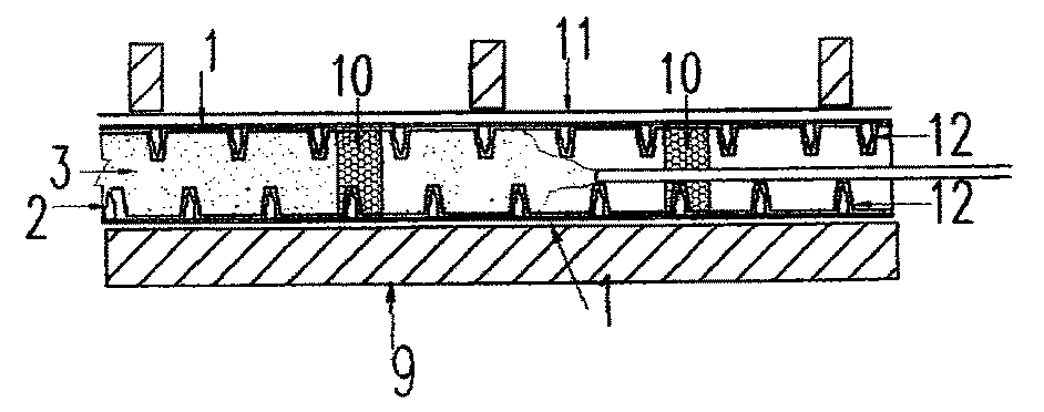
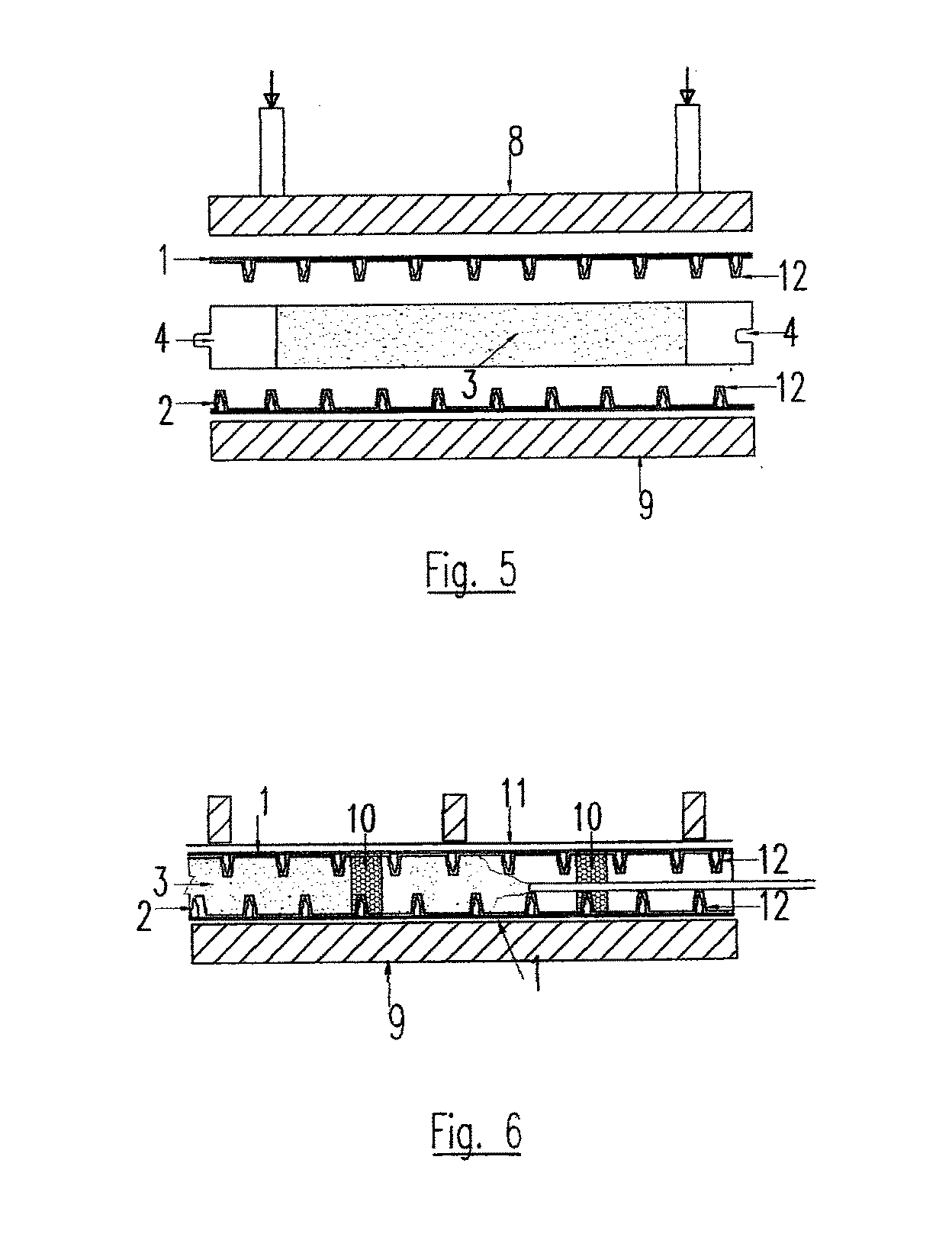
[0030]FIG. 1 is used to illustrate the fundamental concept of the present invention. It consists of first and second outer plates (1), preferably of steel, formed with a plurality of nails (2) pre-punched from these plates (1), and an inner elastomer core (3) as filler preferably made from polyurethane or polyisocyanurate foam material. The first and second outer metal plates (1) here shall be termed “nail-plates”(1) to facilitate easy description of the present invention. The plurality of nails (2) pre-punched from the first and second outer metal nail-plates (1) provide the solution to achieving a coherent integration between the outer metal nail-plates (1) and inner core (3) of a composite member by way of “gripping” action as well as providing an increase in surface area of contact between the outer metal nail-plates (1) and the inner elastomer core (3). The effectiveness of the “grip” is a function of the density and length of the nails (2). The denser and longer the nails (2) ...


PUM

PropertyMeasurementUnit
Flame retardantaaaaaaaaaa

Abstract

A composite structural system comprising first and second outer plates and an inner core of elastomer wherein the outer plates are formed with a plurality of nails pre-punched from the plates to provide coherent integration between the outer plates and the inner elastomer core and are fabricated either by a Post-Sandwich method or a Pre-Sandwich method

Description

FIELD OF THE INVENTION[0001]This invention relates to a composite structural system for construction industry, in particular it relates to composite structural member comprising outer metal plates sandwiching an inner elastomer core.BACKGROUND OF THE INVENTION[0002]Over the years, the use of composite structural system has become more apparent in the construction industry as opposed to conventional systems by using reinforced concrete, steel, timber or bricks. The advantage of the composite system over the use of conventional methods lies in its high strength / weight ratio. The basis of a composite structural system typically comprises a member with outer metal plates sandwiching an inner elastomer core.[0003]There are several methods in existence in the making of the composite structural component in the construction industry, as illustrated in the following prior art documents:—[0004]US Pat. No. 6,050,2008 published on Apr. 18, 2000 which discloses a composite structural laminate c...

Claims


Application Information

Patent Timeline
IPC IPC(8): B32B3/26B32B27/38B32B9/04B32B15/04B32B7/08B32B37/18
CPCE04C2/292E04F15/18E04F13/04E04F15/182Y10T428/31678Y10T428/249953Y10T428/31504Y10T428/31511F16B15/0046
Inventor WONG, CHIANG HENG
Owner WONG CHIANG HENG
Why Eureka
Try Eureka