Vehicle control device and method of controlling vehicle

a technology of vehicle control and control device, which is applied in the direction of hybrid vehicles, process and machine control, instruments, etc., can solve the problems of wasting electric power that is originally provided to heat catalysts, affecting the efficiency of the catalyst, and forming likely dew

Active Publication Date: 2012-01-05
TOYOTA JIDOSHA KK
View PDF7 Cites 30 Cited by
  • Summary
  • Abstract
  • Description
  • Claims
  • Application Information

AI Technical Summary

Benefits of technology

[0013]The present invention provides a control device for a vehicle and a method for controlling a vehicle that prevent failure caused by electric leakage in an EHC while reducing exhaust emissions.

Problems solved by technology

Accordingly, when the internal combustion engine is left unoperated for a long period, dew is likely to be formed as a result of condensation especially in an exhaust passage of the internal combustion engine.
Consequently, electric leakage may occur.
When the electric leakage occurs upon the energization of the EHC, or when the EHC is energized even in a situation where the electric leakage is likely to occur, a portion of electric power that is originally provided to heat the catalyst may be wasted.
In addition, since the vehicle itself (i.e. a body or a chassis) or the exhaust passage can be electrically charged, a driver may get an electric shock by contacting the vehicle body while driving the vehicle, although a degree of shock may vary.
However, such a measure in terms of hardware is insufficient to prevent the electric leakage or a crack in the exhaust passage that is primarily caused by the condensed water.
In addition, since the device is developed on the basis of a technical idea that emphasizes prevention of an abnormality, it is difficult with the device to accurately detect the occurrence of the abnormality.
If the device that is described in JP-A-8-210217 is examined with the above issue in mind, the possible occurrence of the electric leakage is high in the hybrid vehicle in which dew is likely to be formed due to a lack of consideration that the device may be installed in the hybrid vehicle.
However, since such a technical idea is developed without any consideration of the electric leakage, it is impossible to prevent the electric leakage described above.
As it has been discussed so far, the above devices have a technical problem that it is difficult to prevent failure caused by the electric leakage if the EHC is installed in the vehicle.
Needless to say, if only the prevention of the electric leakage is taken into consideration, the reduction in exhaust emissions upon startup of the internal combustion engine is not sufficiently achieved.

Method used


Image

  • Vehicle control device and method of controlling vehicle
  • Vehicle control device and method of controlling vehicle
  • Vehicle control device and method of controlling vehicle

Examples


Embodiment Construction

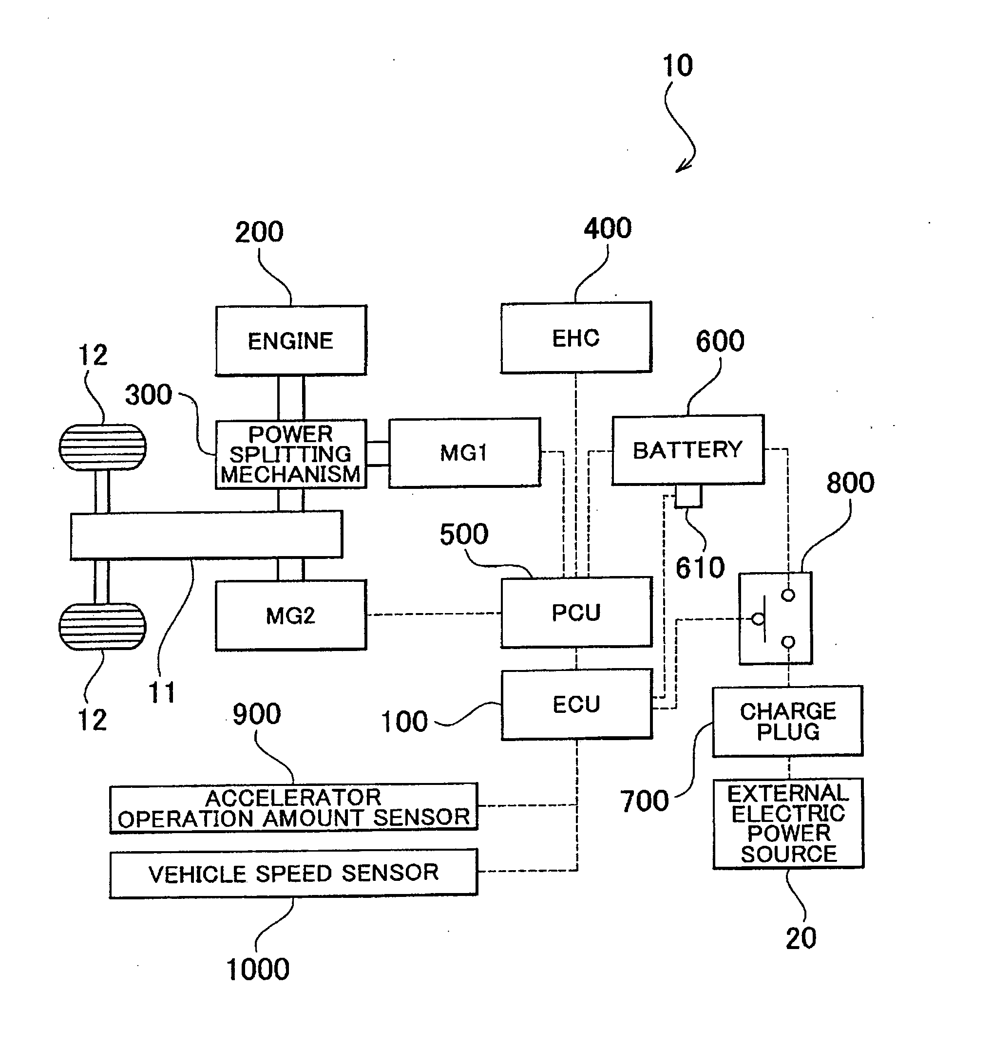
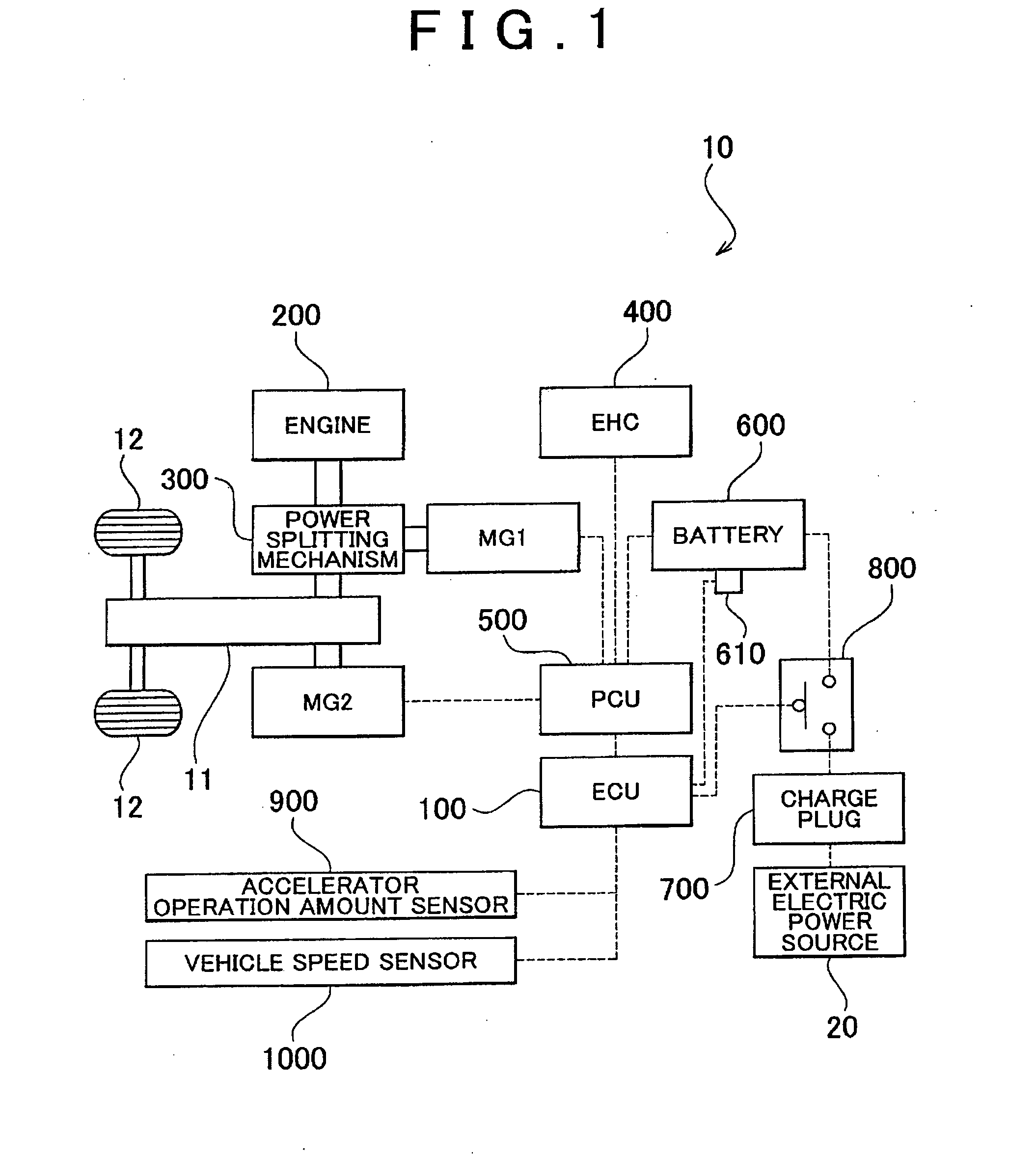
[0051]Embodiments of the present invention will be described with reference to the drawings. A hybrid vehicle 10 according to a first embodiment of the present invention will be described with reference to FIG. 1. FIG. 1 is a schematic block of the configuration of the hybrid vehicle 10.

[0052]The hybrid vehicle 10 in FIG. 1 is an example of the “vehicle” and the “hybrid vehicle” according to the present invention, and includes a speed reduction mechanism 11, a wheel 12, an ECU 100, an engine 200, a motor generator MG1 (hereinafter abbreviated as “MG1” accordingly), a motor generator MG2 (hereinafter abbreviated as “MG2” accordingly), a power splitting mechanism 300, an EHC 400, a power control unit (PCU) 500, a battery 600, a charge plug 700, a relay circuit 800, an accelerator operation amount sensor 900, and a vehicle speed sensor 1000.

[0053]The speed reduction mechanism 11 is a gear mechanism that includes a differential gear (not shown) and the like and that can be rotated in ac...


PUM


Abstract

In a hybrid vehicle, an ECU executes drive control of an EHC. For the control, the ECU first executes low-voltage drive in which a drive voltage is reduced to 50 V when an energization request of the EHC is made. Then, based on a resistance value of the EHC, the ECU detects whether or not electric leakage is caused by dew formation of condensed water in the EHC. Consequently, if the electric leakage is detected, the energization of the EHC is inhibited. If electric leakage is not detected, the drive voltage Vd is increased to 200 V for normal drive to heat a catalyst by the EHC.

Description

BACKGROUND OF THE INVENTION[0001]1. Field of the Invention[0002]The present invention relates to a control device for a vehicle that includes an electrically heated catalyst (EHC) and a method for controlling the vehicle.[0003]2. Description of the Related Art[0004]For example, Japanese Patent Application Publication No. 8-210127 (JP-A-8-210127) describes a device that prevents electric leakage in an EHC. An exhaust gas control apparatus for an internal combustion engine that is described in JP-A-8-210127 includes an upstream catalyst carrier with a heater function, a downstream catalyst carrier, and a bypass passage through which a portion of exhaust gases bypasses the upstream catalyst carrier and is guided to the downstream catalyst carrier. Accordingly, the temperature increase of the downstream catalyst carrier is promoted. In the above configuration, since a positive, electrode of the heater in the upstream catalyst carrier is positioned above the bypass passage, it is possibl...

Claims


Application Information

Patent Timeline
Patent Type & Authority Applications(United States)
IPC IPC(8): F01N11/00B60W10/08B60W20/00B60W10/06
CPCF01N3/2026F01N11/00F01N2550/22F01N2590/11F01N2900/0422F01N2900/0602F01N2900/1602Y02T10/26Y02T10/47Y02A50/20Y02T10/12Y02T10/40
Inventor WATANABE, TAKASHI
Owner TOYOTA JIDOSHA KK
Why Eureka
Try Eureka