
Electrical and electronic system having an electrical center for a vehicle

a technology electrical centers, applied in the field of electric and electronic systems having an electrical center for a vehicle, can solve the problems of increasing design and manufacturing costs, increasing increasing the number of cut leads, so as to reduce the possibility of connection failure, reduce the size of the wire, and reduce the effect of wires

Active Publication Date: 2012-01-05
APTIV TECH LTD
View PDF4 Cites 16 Cited by
  • Summary
  • Abstract
  • Description
  • Claims
  • Application Information

AI Technical Summary

Benefits of technology

[0011]In accordance with an embodiment of the invention, the data bus replaces the conventional wire harness that electrically connects the control module and electrical center of prior art systems. The data bus allows for the reduction of wires and the use of smaller connectors. The reduction of wires reduces the possible of connection failures and allows the size of the passageway in the firewall between the control module and electrical center to be smaller in size. In addition, the integrated circuits being on the bus interface unit, which could be a separate daughter board plugged into the main PCB, eliminates the need for high current circuits integrated into the bus interface unit, therefore reducing manufacturing complexity.

Problems solved by technology

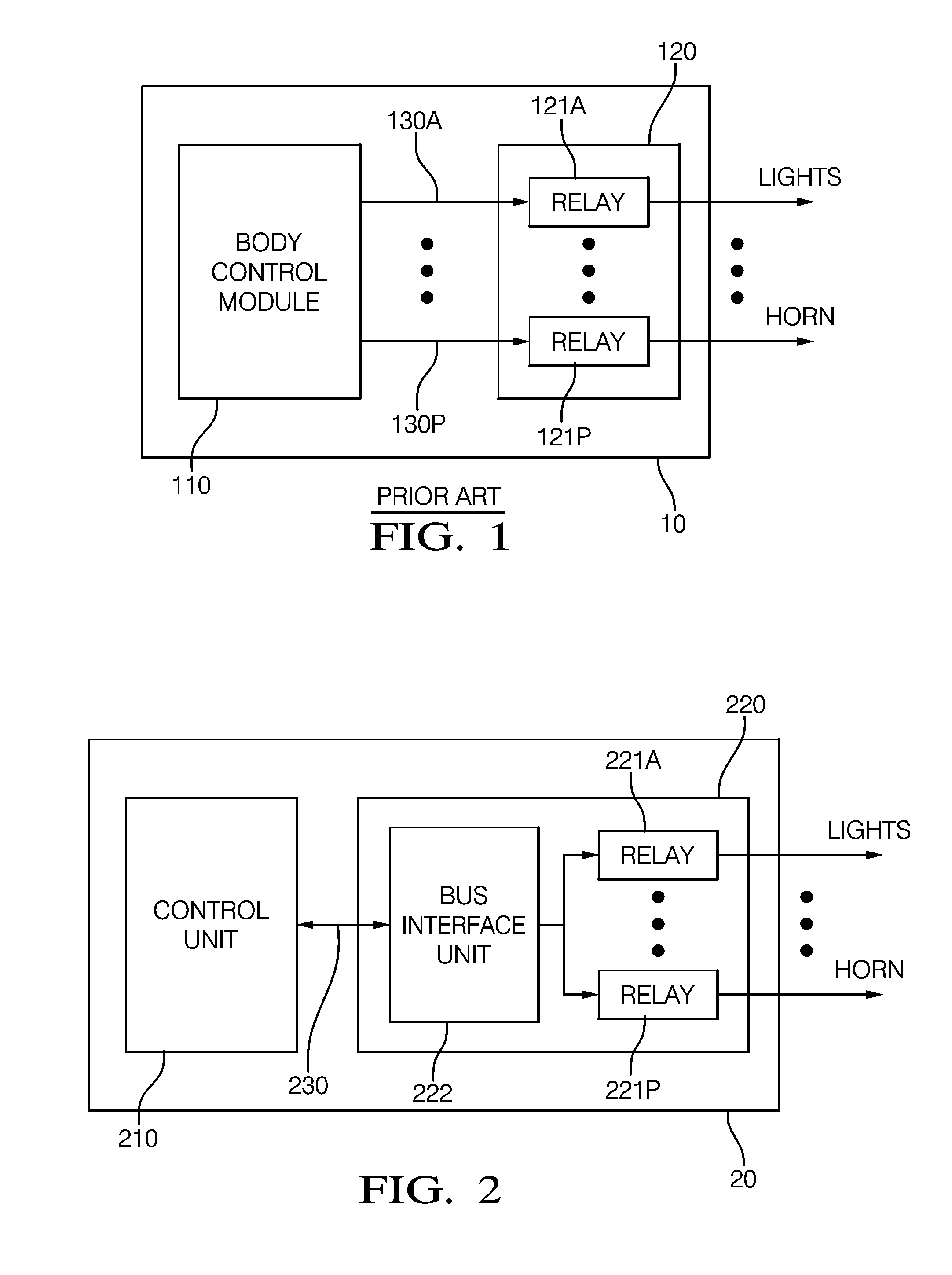
Therefore, the number of leads required to connect the body control module 110 to the relays 121A-121P may be much greater than 16 pairs resulting in a large number of cut leads, terminal ends, and connectors, thus increasing the possibility of connection failures.
In addition, the electrical and electronic system 10 shown in FIG. 1 may be susceptible to electromagnetic interference and requires additional high-frequency ground shielding, which increases design and manufacturing costs.

Method used


Image

  • Electrical and electronic system having an electrical center for a vehicle
  • Electrical and electronic system having an electrical center for a vehicle
  • Electrical and electronic system having an electrical center for a vehicle

Examples


Embodiment Construction

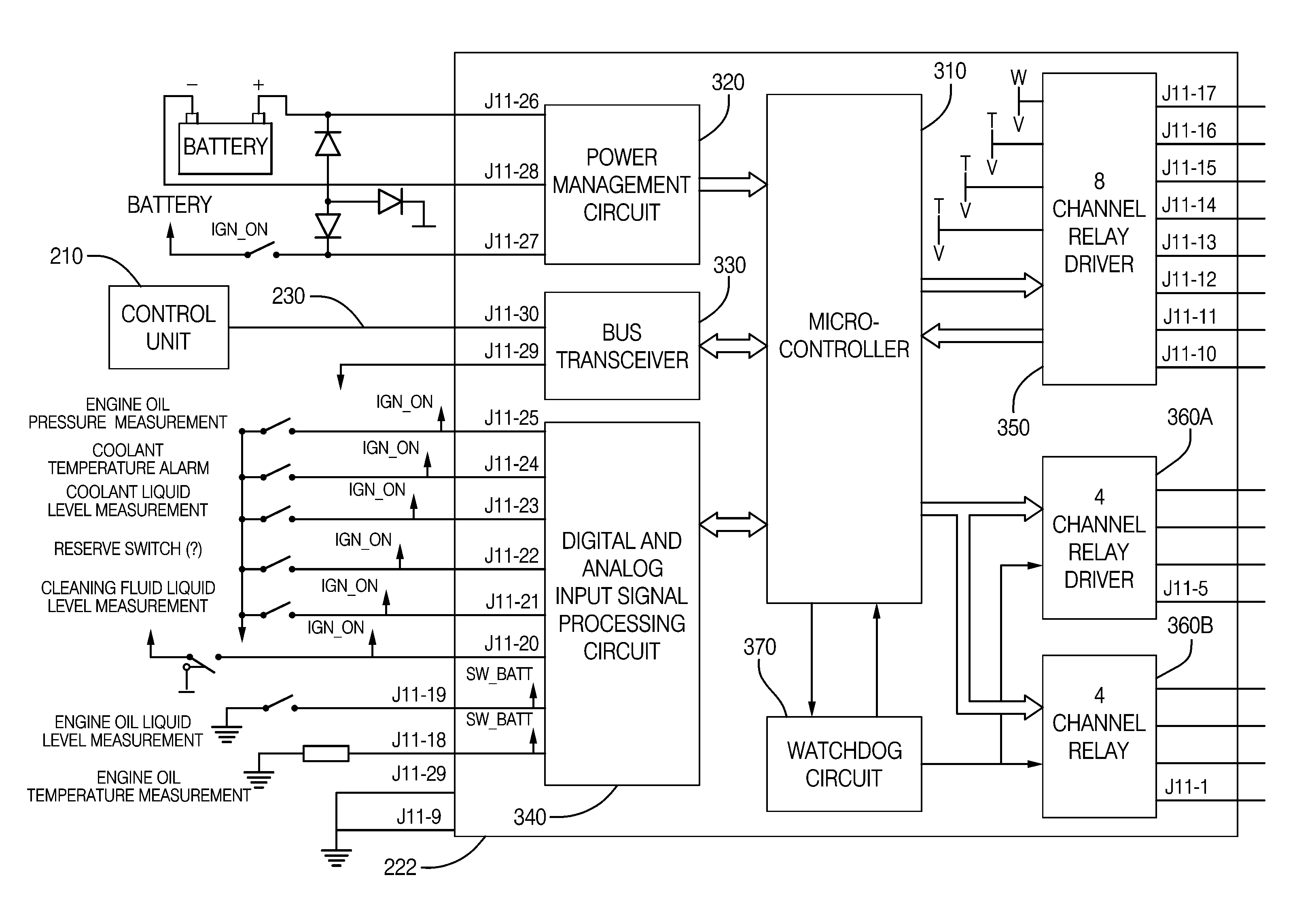
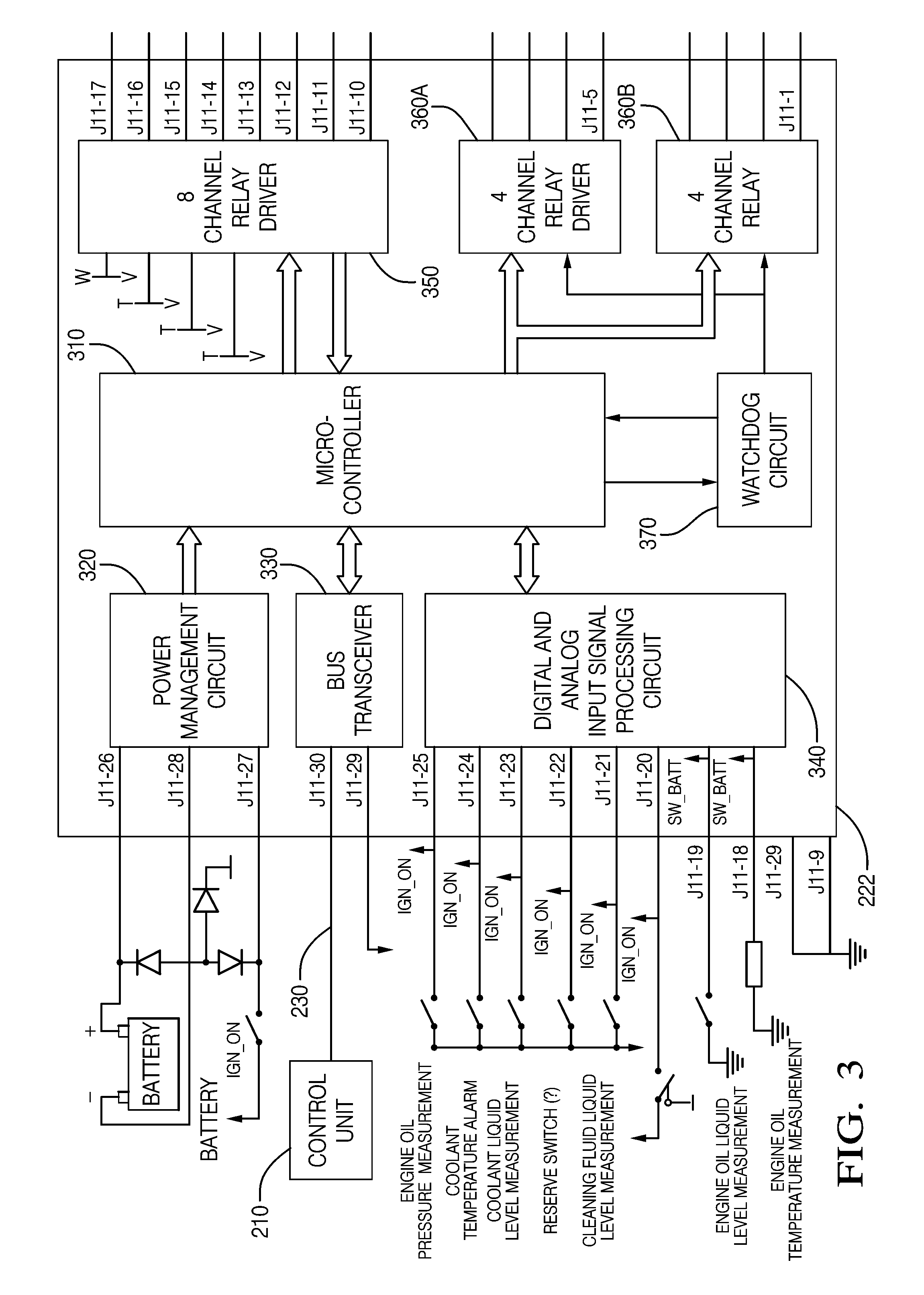
[0018]Shown in FIG. 2 is an embodiment of the invention of an electrical and electronic system 20 for a motor vehicle. The electrical and electronic system 20 includes a control unit 210 and a bussed electrical center 220 remote from the control unit 210. The bussed electrical center 220 includes a bus interface unit 222 and a main printed circuit board (PCB) having a plurality of control devices such as relays 221A-221P and fuses. The relays 221A-221P selectively supply or disconnect power to the associated vehicle electrical circuit (not shown) based on instructions from the control unit 210. The control unit 210 is coupled to the bus interface unit 222 by way of a data bus 230. The respective leads of the relays 221A-221P are coupled to the bus interface unit 222 within the bussed electrical center 220. The bus interface unit 222 may be a separate daughter printed circuit board that plugs into the main PCB.

[0019]In the embodiment shown in FIG. 2, the control unit 210 communicates...


PUM


Abstract

An electrical and electronic system having a control unit connected to a remotely located electrical center by way of a data bus. The electrical center includes a bus interface unit and a main printed circuit board having a plurality of control devices such as relays, which selectively activate vehicle electrical circuits based on instructions from the control unit. The bus interface unit is that of a daughter board configured to be plugged into the main board of the electrical center, such as a Local Interconnect Network (LIN) interface board, and the data bus may be a LIN bus.

Description

RELATED APPLICATIONS[0001]This application is based on and claims the benefit of priority from Chinese Patent Application No. 201010225192.8, filed on Jul. 5, 2010, the contents of which are incorporated by reference.TECHNICAL FIELD OF INVENTION[0002]The invention relates to vehicle electronic technology; more particularly, to an electrical and electronic system having an electrical center for a vehicle.BACKGROUND OF INVENTION[0003]The electrical center of a motor vehicle is the heart of power distribution and circuit protection in the vehicle. The primary purpose of the electrical center is to provide a centralized location for electrical power and signal distribution for the associated vehicle circuits and electrically operated components. The electrical center includes a power distribution system and a printed circuit board assembly for controlling the fuses and switching devices such as relays. The electrical center is in communication with a body control module.[0004]The body c...

Claims


Application Information

Patent Timeline
Patent Type & Authority Applications(United States)
IPC IPC(8): G06F13/20
CPCH04L12/40006H04L2012/40215G06F13/385H04L2012/40273H04L2012/40234
Inventor HU, HAWKINGYANG, XIAOJUNXU, JUNJIE
Owner APTIV TECH LTD
Learn More