
Electronic blast control system for multiple downhole operations

Inactive Publication Date: 2012-01-12
ANDERSON OTIS R
View PDF5 Cites 42 Cited by
  • Summary
  • Abstract
  • Description
  • Claims
  • Application Information

AI Technical Summary

Benefits of technology

[0010]It is a principal feature of the present invention to provide a novel blast control system that is capable of selectively and sequentially activating or firing two or more well service tools that are simultaneously run into a well by a single tool conveying system such as a wire-line tool conveyor, a coiled tubing tool conveyor, a conduit type tool conveyor or any other conveyance system that is in use at the present time.
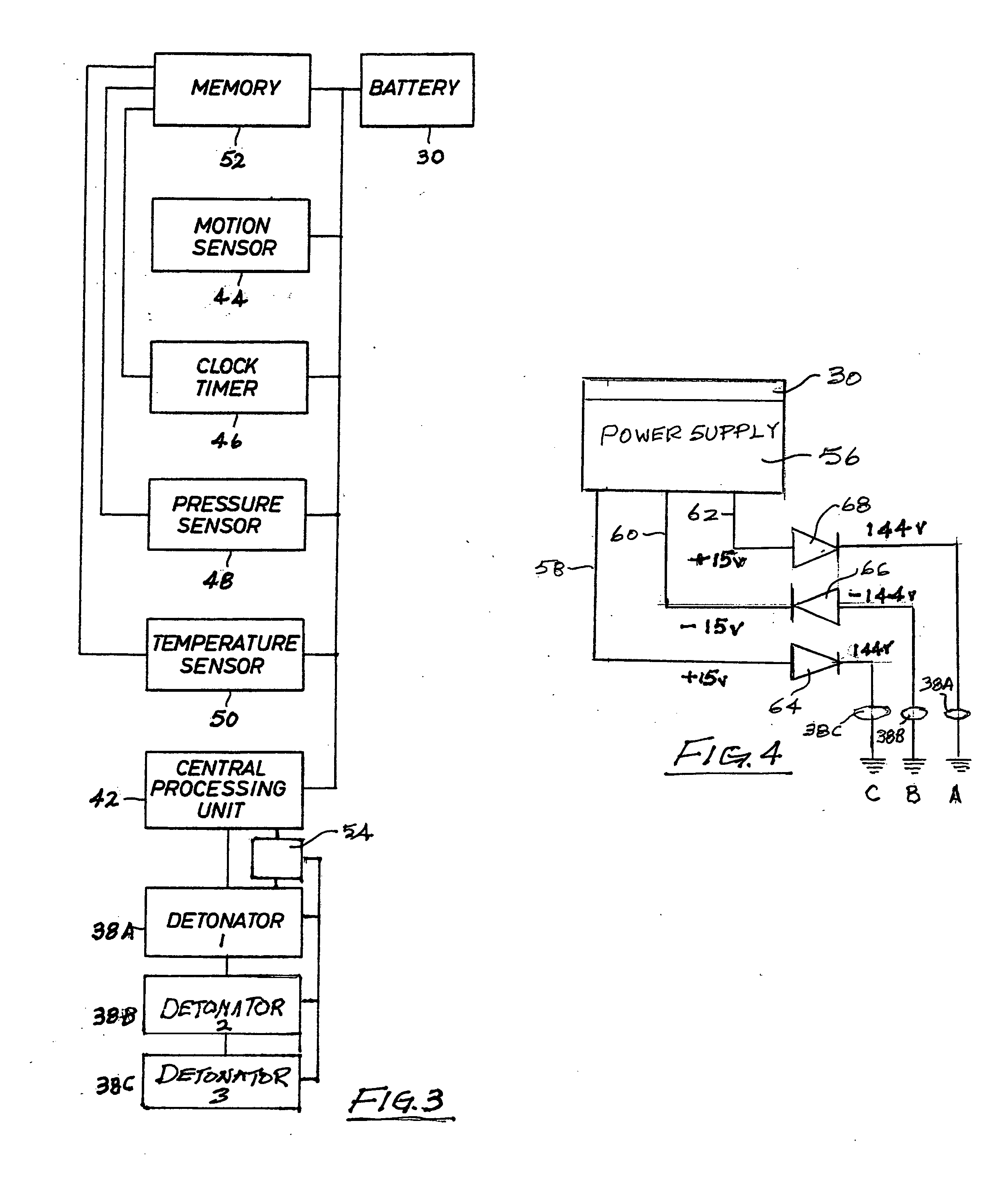
[0014]Briefly, the various objects and features of the present invention are realized through the provision of U.S. Pat. No. 5,369,579 of Otis R. Anderson is incorporated by reference herein for all purposes. Many of the features of the '179 patent will be employed together with the features of the present invention to provide a multi-shot downhole well servicing operation wherein two or more tools are run into a well casing simultaneously by wireline equipment, typically known as “slick line” and are activated sequentially. This blast control system is primarily designed for serial energization or firing of spaced series related perforating guns; however it is not intended that the present invention be limited solely to perforating guns. Other downhole activities in wells, such as setting packers and anchors or cutting well casing can also be performed in a manner that takes advantage of running tools into a well a single time for the conduct of multiple downhole activities that utilize explosive generated gas pressure or explosive actuation of components. When the multi-shot tools are in the form of casing perforation guns each having multiple shaped charges, the perforation guns are run into the well in the same run and are each positioned at a designed depth. The perforation guns are activated responsive to voltage of designed polarity, positive or negative, and adjacent perforation guns or other well service tools are responsive to voltage of the opposite polarity. The reversed polarity voltage is achieved by reversing circuit diodes that permit the flow of boosted battery power from a battery supply that is on board the instrument or tool of the blast control system. Obviously, in the case of wells, the first tool of a spaced series of tools will be actuated by voltage of a selected polarity, positive or negative. The next succeeding tool will be actuated by voltage of opposite polarity, negative or positive, thus ensuring against detonation or energization of adjacent well service tools.

Problems solved by technology

It is imperative that a downhole explosive device be permitted to fire only when it is properly located at designed depth within the well; otherwise, the well casing could be perforated at the wrong depths or well service personnel could experience significant danger.
Though blast control systems having electric line supply and control are used, such systems are quite expensive and difficult because of the necessity for providing electrical supply and control lines extending from the surface to the depth for the downhole activity, which is typically near the bottom of the well.
Independently running a number of well tools into a well in this fashion is an expensive proposition due to the significant rig time and labor costs that are involved.

Method used


Image

  • Electronic blast control system for multiple downhole operations
  • Electronic blast control system for multiple downhole operations
  • Electronic blast control system for multiple downhole operations

Examples


Embodiment Construction

[0023]The term “blast control” as used herein is intended to mean a control system for two or more electronically initiated and sequentially activated devices that develop an explosive force or rapid generation of combustion gas in the downhole environment for the purpose of doing desired work. The work may take the form of casing perforation by sequential or series explosive shaped charges that develop specifically oriented hot gas jets for perforation of well casing or make take the form of packers, anchors and the like which are activated to set positions by explosive generation of gas.

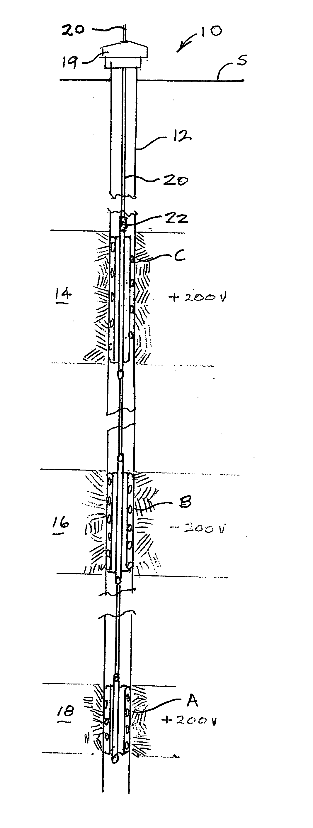
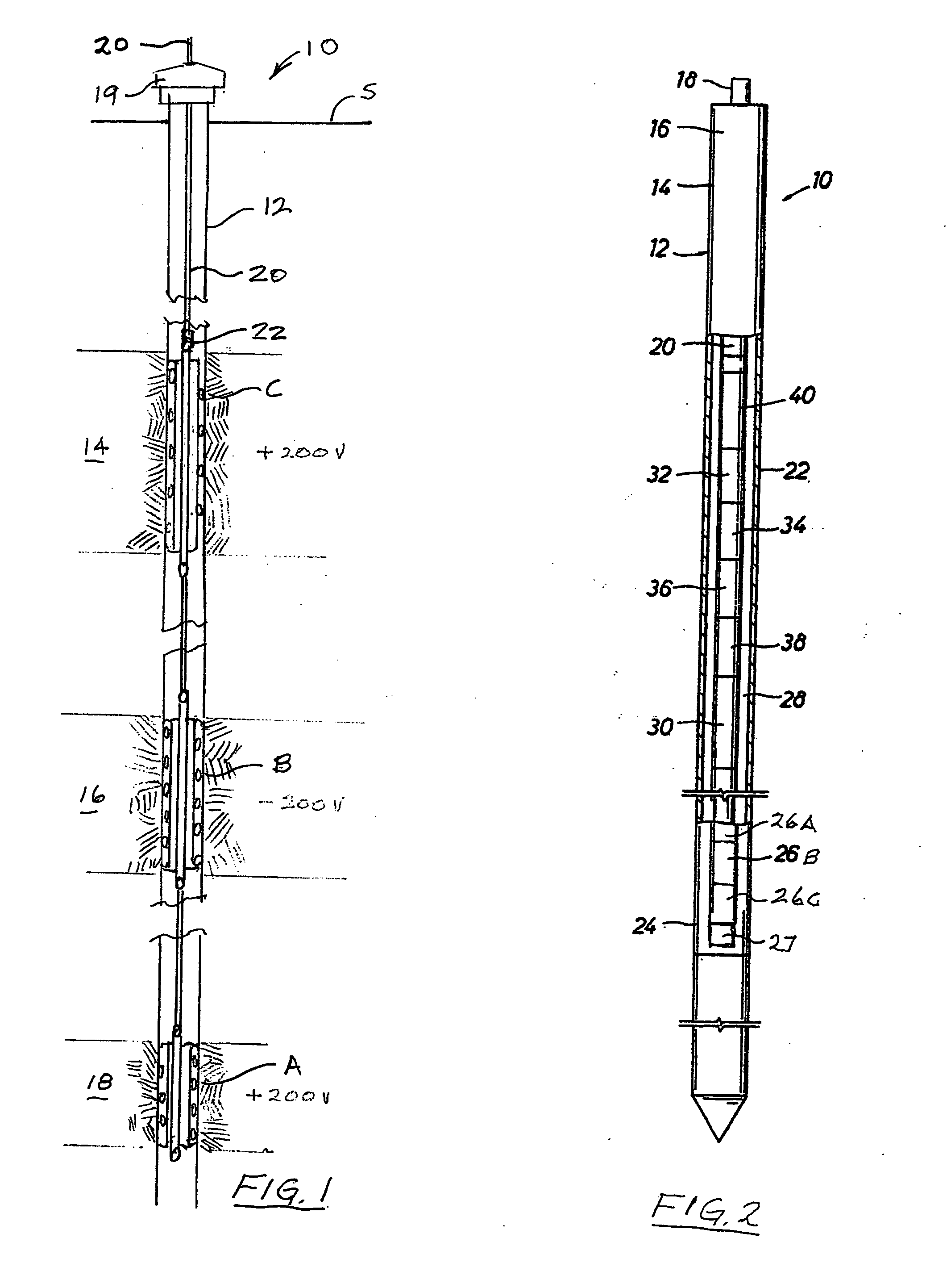
[0024]Referring now to the drawings and first to FIG. 1, a well for production of petroleum products such as crude oil and natural gas is shown generally at 10 and incorporates a well casing 12 that lines a borehole intersecting a plurality of subsurface production formations 14, 16 and 18. The well casing is connected with a wellhead 19 which extends above the surface “S”. Though not shown, a wire...


PUM


Abstract

A system for multiple subsurface operations which are carried out in a well bore by means of two or more well tools having explosive or gas generating charges which are electronically initiated for accomplishing any number of other downhole well activities. Two or more well service tools are simultaneously run into a well on a single wire-line and are located at predetermined positions. An electronic blast control system having safety parameters, including time, movement, pressure and the like to ensure safe running and independent firing of the tools. The blast control system permits controlled energization of the explosive charges only when all of the programmed parameters have been met and causes sequential or serial electronic firing of the explosive devices independently of one another by positive and negative voltages.

Description

RELATED PROVISIONAL APPLICATION [0001]Applicant hereby claims the benefit of U.S. Provisional Patent Application No. 61 / 399,091 filed on Jul. 7, 2010 by Otis R. Anderson and entitled “Electronic Blast Control System For Multiple Downhole Operations”, which Provisional Patent Application is incorporated by reference herein for all purposes.BACKGROUND OF THE INVENTION[0002]1. Field of the Invention[0003]This invention relates generally to subsurface operations which are carried out in a well bore by means of one or more spaced explosive charges which are typically contained within spaced blast joints or blast guns and are electronically initiated for doing such work as perforation of well casing by means of shaped charges, setting of packers by means of explosive generated pressure, and for sequentially accomplishing any number of other downhole well activities. More specifically, the present invention concerns a method and apparatus for electronically controlling well service operati...

Claims


Application Information

Patent Timeline
IPC IPC(8): E21B43/1185F42B99/00F23Q21/00F42D1/055
CPCE21B43/1185F42D3/04F42D1/055
Inventor ANDERSON, OTIS R.
Owner ANDERSON OTIS R
Learn More