High pressure drop muffling system

a muffling system and high pressure drop technology, applied in the field of muffling systems, can solve the problems of excessive noise, high mach number of flow exhausted into the by-pass stream, and limited conventional design

Active Publication Date: 2012-01-12
GENERAL ELECTRIC CO
View PDF2 Cites 38 Cited by
  • Summary
  • Abstract
  • Description
  • Claims
  • Application Information

AI Technical Summary

Problems solved by technology

The problem: In least some known gas turbine engines, during engine operation occurring in some off-design operating conditions, the compressor may pump more air than is required for needs to include the combustion process.
Such known conventional designs share limitations in that the Mach number of the flow exhausted into the by-pass stream may be high and also that the noise generated may be excessive.
Furthermore, conventional designs are limited in that they only work when part of systems having metallic flow path structures that can handle the hot compressor air that is being routed through the TBV system.
Additionally, some conventional systems are limited in that all the pressure loads in are managed by relatively few components causing high aero-mechanical loads and a potential for lower fatigue lives for those components.

Method used


Image

  • High pressure drop muffling system
  • High pressure drop muffling system
  • High pressure drop muffling system

Examples


Embodiment Construction

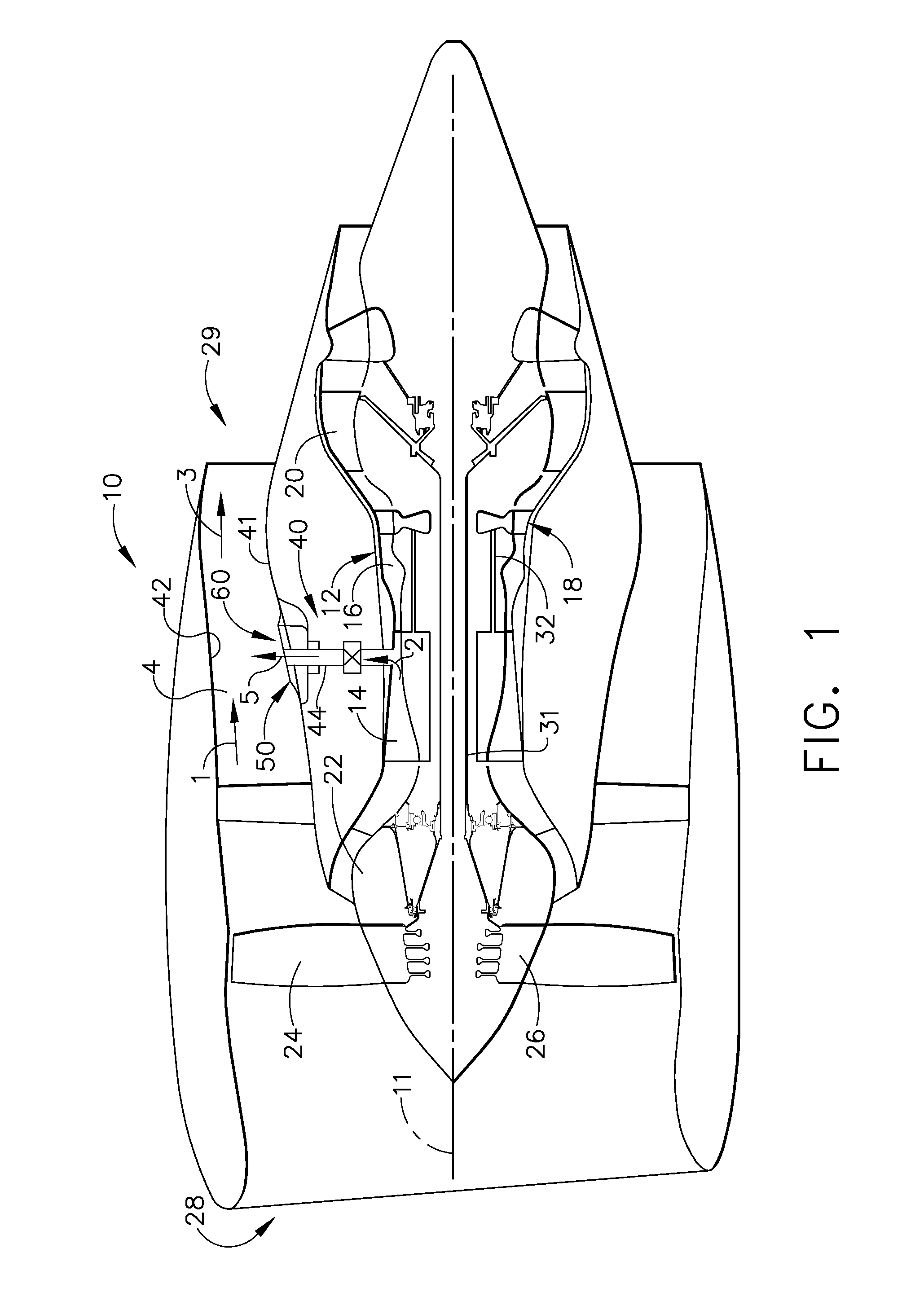
[0015]Referring to the drawings wherein identical reference numerals denote the same elements throughout the various views, FIG. 1 shows a schematic cross-sectional view of an exemplary gas turbine engine assembly 10 having an exemplary vent system 40. FIG. 1 shows the gas turbine engine assembly 10 having a longitudinal axis 11. The gas turbine engine assembly 10 includes a core gas turbine engine 12 that includes a high-pressure compressor 14, a combustor 16, and a high-pressure turbine 18. In the exemplary embodiment shown in FIG. 1, the gas turbine engine assembly 10 also includes a low-pressure turbine 20 that is coupled axially downstream from core gas turbine engine 12, and a fan assembly 22 that is coupled axially upstream from core gas turbine engine 12. Fan assembly 22 includes an array of fan blades 24 that extend radially outward from a rotor disk 26. In the exemplary embodiment shown in FIG. 1, engine 10 has an intake side 28 and an exhaust side 29. In the exemplary emb...


PUM


Abstract

A system for venting a high-pressure flow stream is disclosed, the system comprising a device having a plurality of orifice plates, each orifice plate having a plurality of orifices, wherein the plurality of orifice plates are oriented relative to each other such that the pressure of the flow stream substantially drops.

Description

BACKGROUND[0001]Embodiments are provided that relate generally to muffling systems, and more specifically to muffling systems and apparatus capable of inducing high pressure drops and desirable flow properties. As used herein, the term “fluid” includes gases and liquids.[0002]In a gas turbine engine, air is pressurized in a compression module during operation. The air channeled through the compression module is mixed with fuel in a combustor and ignited, generating hot combustion gases which flow through turbine stages that extract energy therefrom for powering the fan and compressor rotors and generate engine thrust to propel an aircraft in flight or to power a load, such as an electrical generator.[0003]Within at least some known gas turbine engines, a portion of high-pressure air, such as, for example, bleed air from a compressor, is extracted or bled from the compressor for various needs. These needs include, for example, compressor flow bleeding which is used in order to improv...

Claims


Application Information

Patent Timeline
Patent Type & Authority Applications(United States)
IPC IPC(8): E04F17/04
CPCF02K3/075F05D2260/96F02C6/08Y10T137/85938
Inventor KLASING, KEVIN SAMUELFINTEL, BRADLEY WILLISGLESSNER, JOHN CARLMASON, JEFFREY LEEPOTOKAR, CHRISTOPHER JONPROCTOR, ROBERT
Owner GENERAL ELECTRIC CO
Why Eureka
Try Eureka