UV disinfecting device

Inactive Publication Date: 2012-01-12
KONINKLIJKE PHILIPS ELECTRONICS NV
View PDF12 Cites 51 Cited by
  • Summary
  • Abstract
  • Description
  • Claims
  • Application Information

AI Technical Summary

Benefits of technology

[0011]According to the invention, there is thus proposed a disinfecting device with an interior volume that is illuminated by UV light from a specially adapted dielectric barrier discharge lamp arranged within the end cover. The lamp is well suited for efficient production of UV light. Further, its geometry with a planar window is well integrated in the container housing. Thus, a very compact device is provided which may efficiently treat objects and/or fluids arranged within the volume.
[0012]According to a preferred embodiment of the invention, the interior volume of the container has cylindrical shape. In the present context this is understood to mean that the cross-section of the interior volume, at least in a central portion over 50% or more of its length, remains the same. Here, the cross-sectional shape may be e.g. circular, square, rectangular or other. For a cylindrical shape, illumination of the volume from the direc

Problems solved by technology

However, up to now UV disinfection has not fo

Method used


Image

  • UV disinfecting device
  • UV disinfecting device
  • UV disinfecting device

Examples


first embodiment

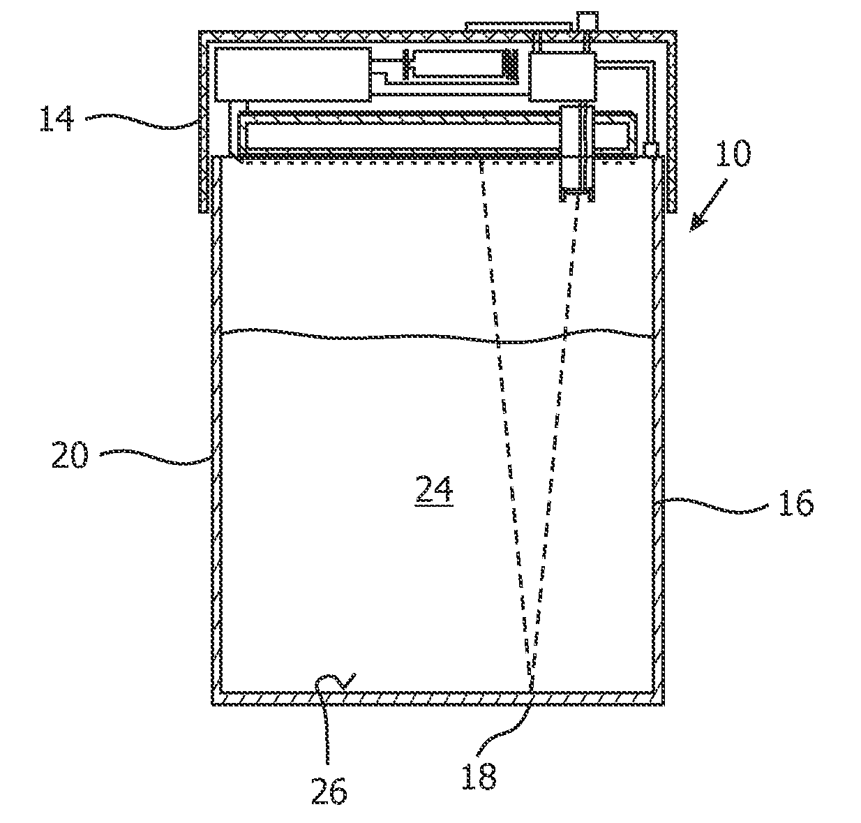
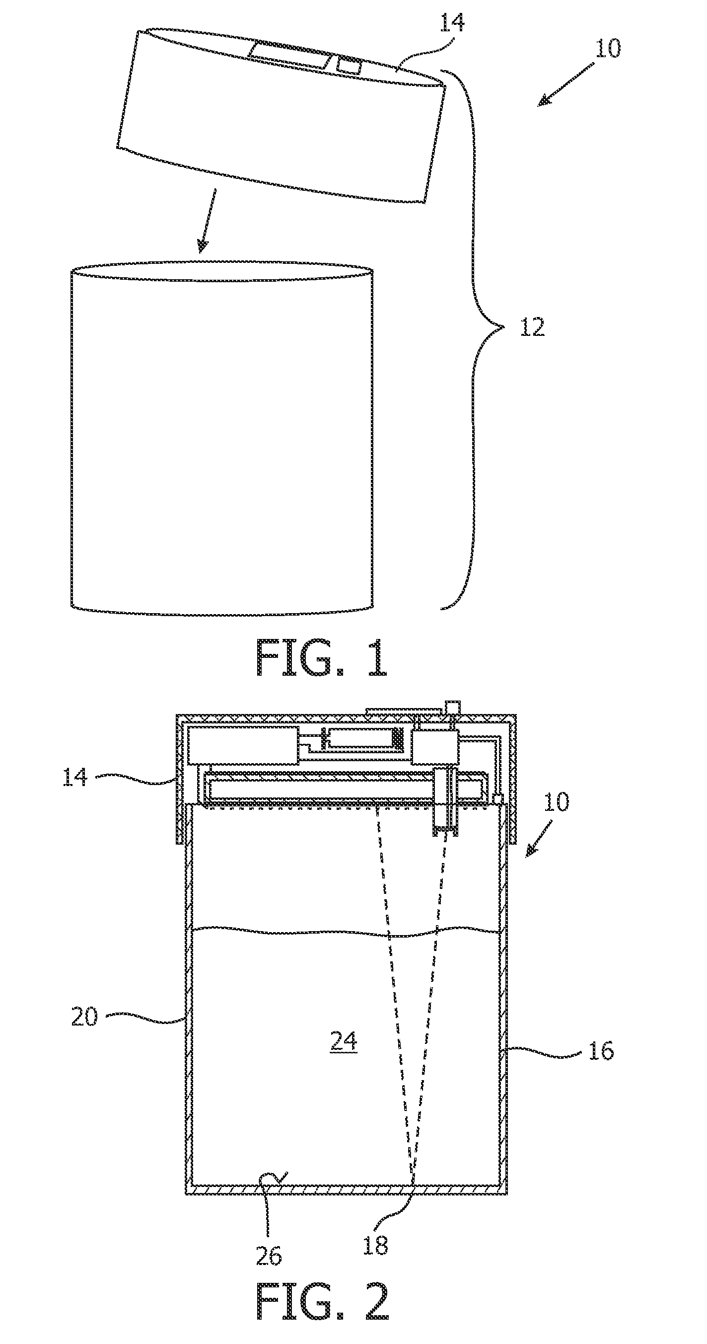
[0033]FIG. 1 shows a disinfection device 10 consisting of a container housing 12 with a detachable top cover 14.

[0034]FIG. 2 shows the device 10 in cross-section. The container housing 12 consists of a side wall 16, a bottom 18 and the detachable lid 14 acting as top cover. As shown in FIG. 2, the side wall 16 and bottom 18 are formed in one piece as a stainless steel container 20. The shape of the side wall 16 is such that it is cylindrical with a constant, circular cross-section over the entire height. Due to its construction as one piece, the container housing 12 is sealed to the side and bottom, such that it may contain a liquid in its interior cavity 24. The side wall 16 and the bottom 18 together form a cup, which may e.g. contain water, and which has a shape and size such that it may be handled as a drinking cup, i.e. used to directly drink from the cup.

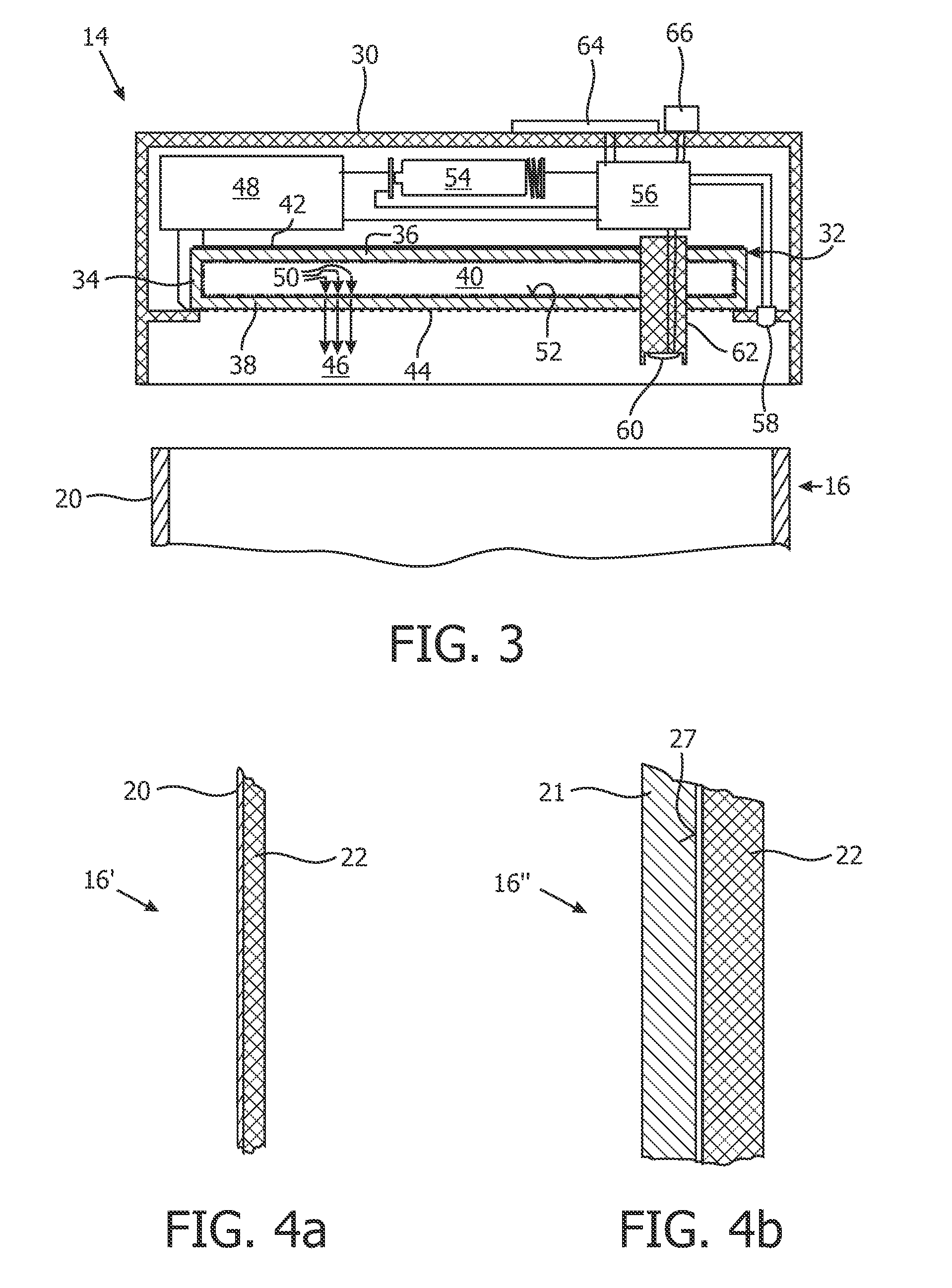
[0035]FIG. 3 shows in an enlarged sectional view of the lid 14 (upper end cover) of the device 10. In a plastic housing 30 t...

third embodiment

[0058]FIG. 7 shows a disinfecting device 210. The alternative device 210 differs from the above discussed embodiments in that it not only contains a detachable top cover 14 including a dielectric barrier discharge lamp and driver circuitry, but also a quasi identical detachable bottom cover 214 which also comprises a dielectric barrier discharge lamp and associated driver circuitry.

[0059]As in the above embodiments, side wall 16 of the container housing 12 is preferably of stainless steel (but other materials as discussed above may alternatively be chosen).

[0060]In the disinfecting device 210 according to the third embodiment, an object 125 placed within the inner volume 24 or a liquid contained in the inner volume 24 (in this case, the connection between the detachable lower lid 214 and the side wall 16 of the container housing 12 is sealed by gaskets to prevent leakage) is very efficiently disinfected by UV-C radiation both from above and below. This aids in disinfection of an obj...

second embodiment

[0097]110 second embodiment of disinfecting device

[0098]117 bottom cover

[0099]125 object

[0100]210 third embodiment of disinfecting device

[0101]214 bottom cover

[0102]258 closure sensor

[0103]260 photo sensor


PUM


Abstract

A disinfecting device is proposed that is well suited for household and outdoor use. The device comprises a container housing 12 with an interior volume 24, which may contain an object or a liquid to be disinfected. The container housing 12 comprises a side wall 16 and an end cover 14. A dielectric barrier discharge lamp 32 is provided for emitting ultraviolet light into the volume 24. The lamp 32 comprises a lamp vessel 34 with gas filling and electrodes 42, 44 arranged electrically insulated from the gas filling. An alternating voltage applied to the electrodes 42, 44 causes a discharge in the gas filling. The lamp vessel 34 has a planar window from which during the discharge ultraviolet light 46 is emitted. The window is arranged in the end cover 14.

Description

FIELD OF THE INVENTION[0001]The invention relates to the field of disinfecting devices, and more specifically to a device for disinfecting objects and / or liquids by ultraviolet (UV) light.BACKGROUND OF THE INVENTION[0002]Ultraviolet light may be used for disinfection of liquids or objects. For example, it is known to use UV radiation generated by low-pressure or medium-pressure mercury arc discharge lamps for treatment of waste water. UV-C radiation (with a wavelength of 200-280 nm) achieves disinfection by damaging the DNA of contaminating micro-organisms. However, up to now UV disinfection has not found wide-spread use in household applications.[0003]US-A-2005 / 0258108 describes a container for purifying water. The container has a lid with one or more UV LEDs as radiation source. Also, integrated in the lid is a solar panel and a rechargeable power source to operate the LEDs. The lid is removably attached to the container by way of threads or a snap-fit connection. In alternate emb...

Claims


Application Information

Patent Timeline
IPC IPC(8): A61L2/10G01J1/42
CPCC02F1/325Y02W10/37A61L2/10
Inventor GREUEL, GEORG
Owner KONINKLIJKE PHILIPS ELECTRONICS NV
Why Eureka
Try Eureka