Position detecting apparatus

a position detecting and position technology, applied in the direction of instruments, galvano-magnetic hall-effect devices, galvano-magnetic devices, etc., can solve the problems of difficult enhancement of detection accuracy and misalignment of two sensors, and achieve the effect of reducing the size of the position detecting apparatus, high accuracy and reducing the sensitivity of hall elements

Active Publication Date: 2012-01-12
ASAHI KASEI ELECTRONICS CO LTD
View PDF10 Cites 54 Cited by
  • Summary
  • Abstract
  • Description
  • Claims
  • Application Information

AI Technical Summary

Benefits of technology

[0019]When being used in a combination with a magnetized ring, the position detecting apparatus of the present invention is capable of precisely detecting two signals, which are dependent on the rotation direction, with a phase difference of π/2 independently of the pole pitch of the magnetized ring or the distance to the magnetized ring. Moreover, the position detecting apparatus includes the magnetic plate near the two Hall elements

Problems solved by technology

However, if the two sensors are separately arranged at a distance depending on the pole pitch of the magnetized ring so as to

Method used


Image

  • Position detecting apparatus
  • Position detecting apparatus
  • Position detecting apparatus

Examples


first embodiment

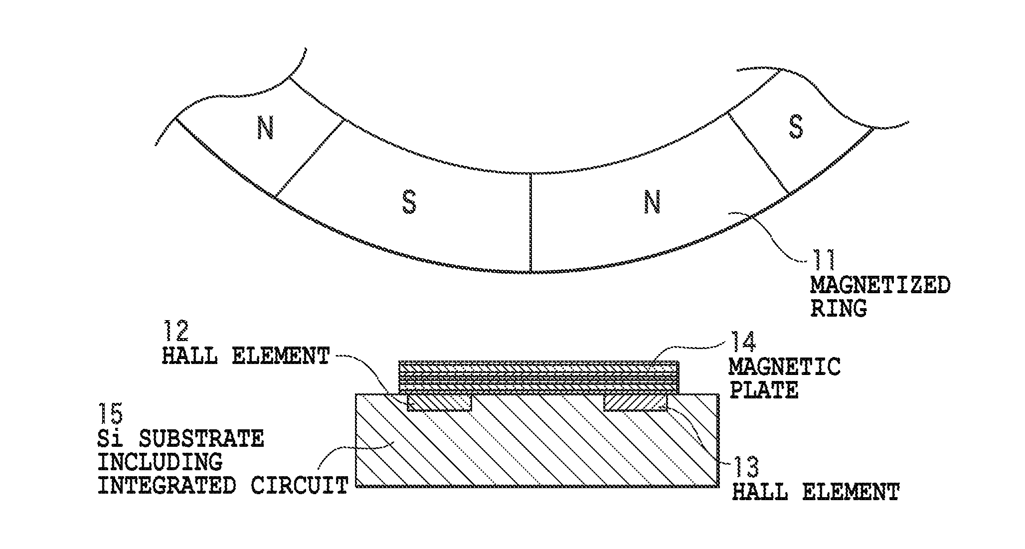
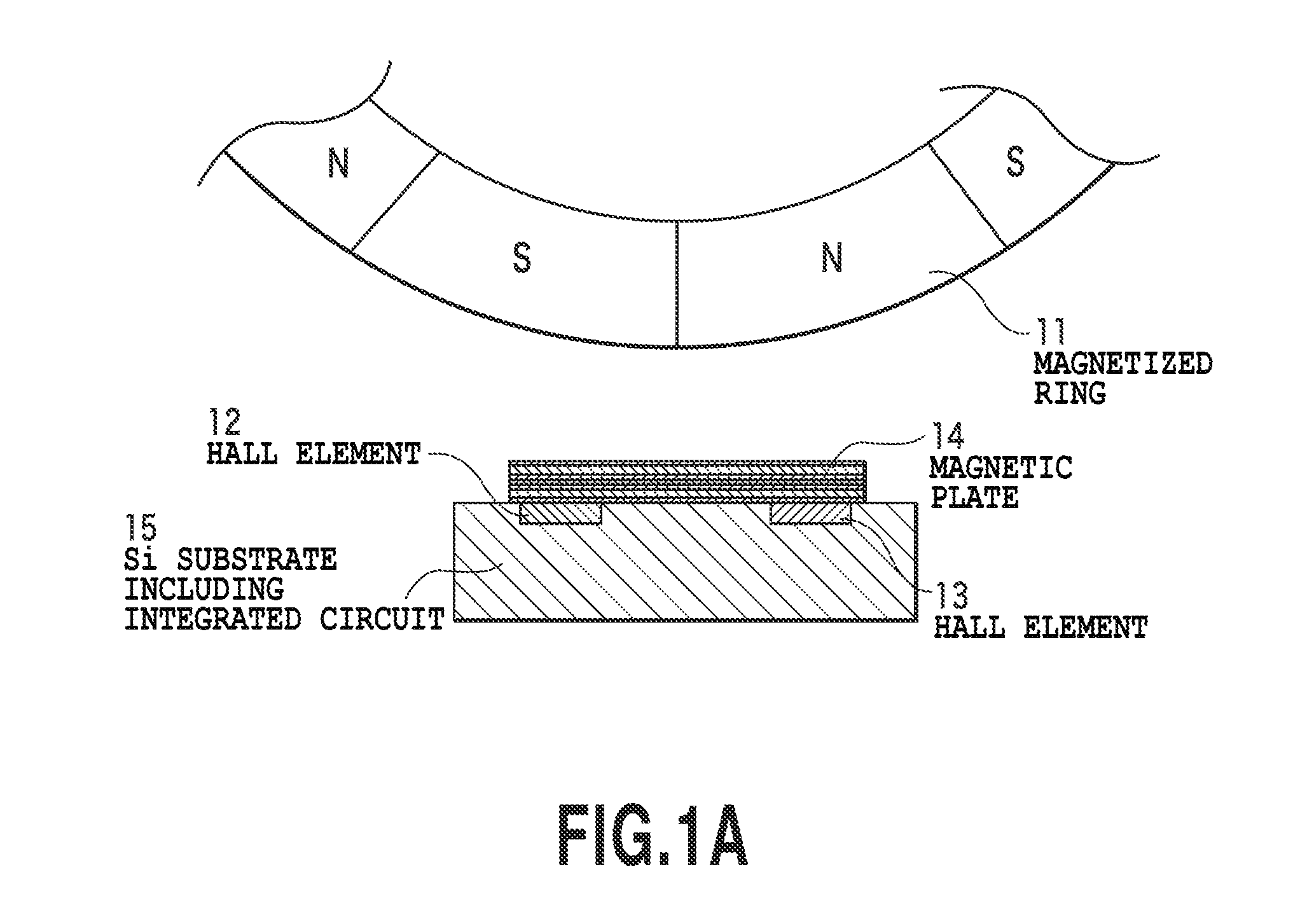
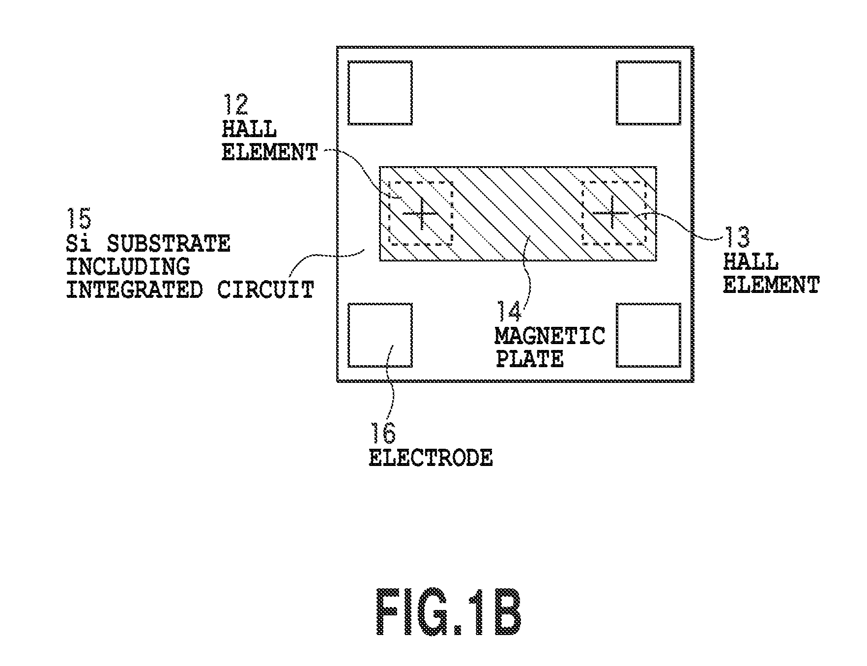
[0033]FIG. 1A is a view for explaining a relationship between a magnetized ring and a Hall IC according to the first embodiment of the present invention. FIG. 1B is a plan view showing the Hall IC of FIG. 1A. FIGS. 1A and 1B are not enlarged views and are not intended to show the dimensional relationship between the magnetic ring and Hall IC. In the Hall IC, two Hall elements are formed on a Si substrate away from each other, and a protective film is provided thereon. Furthermore, a rectangular thin-film magnetic plate 14 made of a Ni—Fe alloy is formed thereon by plating so as to overlap the two Hall elements at both ends. The plane shown in FIG. 1B is a plane positioned in parallel to the circumferential surface of the magnetized ring. The Hall elements 12 and 13 are configured to detect the magnetic flux density in a direction vertical to the plane shown in FIG. 1B. The Hall IC is positioned so that the two Hall elements are located on a straight line extending in a rotation dire...

second embodiment

[0052]FIG. 2 is a view showing a main portion of a Hall IC of a second embodiment of the present invention. This view has a same viewpoint as that of FIG. 1B. In this Hall IC, after two Hall elements are formed close to each other on a Si substrate and a protective film is formed thereon, the substrate is divided into two pieces. The Hall IC includes the two pieces placed with a gap between the Hall elements and thin-film magnetic plates made of Ni—Fe alloy by plating so as to overlap the two pieces. In this drawing, for the purpose of concentrating surrounding magnetic flux onto the Hall elements, each magnetic body 14 has such a planar shape that the width in a direction vertical to a straight line passing through the two Hall elements is large on a side opposite to the Hall elements facing each other and is narrowed near the Hall element. Such a configuration can also provide similar effects to those of FIG. 1B.

[0053]in the position detecting apparatus (Hail IC) of the present in...


PUM


Abstract

The present invention provides a single component implementing highly precise pulse detection for rotational or liner position detecting apparatuses for jog dials and mechanical products. Focusing on the fact that the phase difference between the magnetic fields in circumferential and radial directions generated by a magnetized ring is precisely 90 degrees, a position detecting apparatus of the present invention includes two Hall elements placed at a distance; a protective film provided on magnetic sensitive portions of the two Hall elements to cover the magnetic sensitive portions; a thin-film magnetic plate placed on the protective film to cover the magnetic sensitive portions of the two Hall elements; and further a processing circuit calculating the sum and difference of the signals from the two Hall elements to generate signals having an accurate phase difference of 90 degrees. The position detecting apparatus can therefore detect the rotation direction and precise rotation angle.

Description

BACKGROUND OF THE INVENTION[0001]1. Field of the Invention[0002]The present invention relates to a rotational or linear position detecting apparatus for mechanical products such as industrial machines and automobiles, jog dials of hand-held computing devices, and the like.[0003]2. Description of the Related Art[0004]Known rotary or linear pulse encoders each include a magnetic sensor and a ring or a linear scale facing the ring or linear scale and being magnetized so that the opposite magnetic poles can be alternately arranged at a regular pitch. The magnetic sensor translates the magnetic flux density in a direction passing through the magnetic sensor into Hall output voltage, the magnetic flux density changing along with relative rotation of the ring and the magnetic sensor or relative movement of the scale and the magnetic sensor. The translated analog signal is outputted as pulses through a Schmitt circuit or the like (for example, see ASAHI Hybrid Hall Effect IC EW-series catal...

Claims


Application Information

Patent Timeline
IPC IPC(8): G01B7/30G01R33/07
CPCG01D5/145G01R33/07G01D5/24438G01D2205/40
Inventor OKADA, ICHIRO
Owner ASAHI KASEI ELECTRONICS CO LTD
Why Eureka
Try Eureka