
Eddy current flaw detection probe

a flaw detection and eddy current technology, applied in the field of eddy current flaw detection probes, can solve the problems of insufficient sensitiveness to detect small flaws in ferromagnetic tubes made of carbon steel or the like, inability to accurately detect flaws, adverse effects on the sensitivity of the detector, etc., to achieve the effect of accurately detecting flaws in magnetic tubes, and detecting flaws more accurately

Active Publication Date: 2012-01-12
SUMITOMO CHEM CO LTD
View PDF4 Cites 20 Cited by
  • Summary
  • Abstract
  • Description
  • Claims
  • Application Information

AI Technical Summary

Benefits of technology

[0009]An object of the present invention is to provide an insertion type eddy current flaw detection probe that is capable of accurately detecting flaws in magnetic tubes.
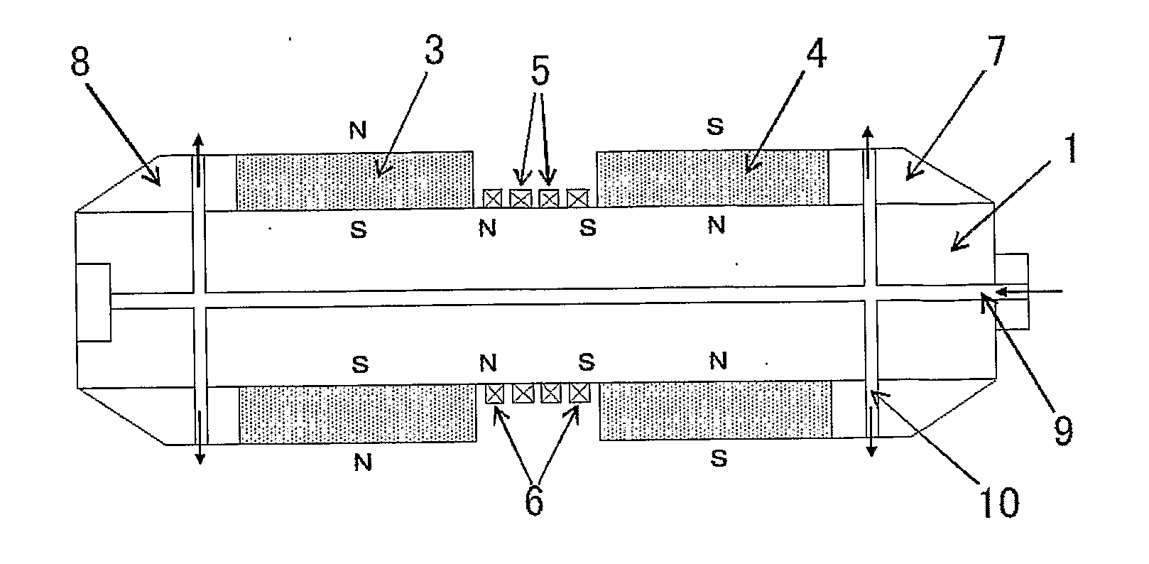
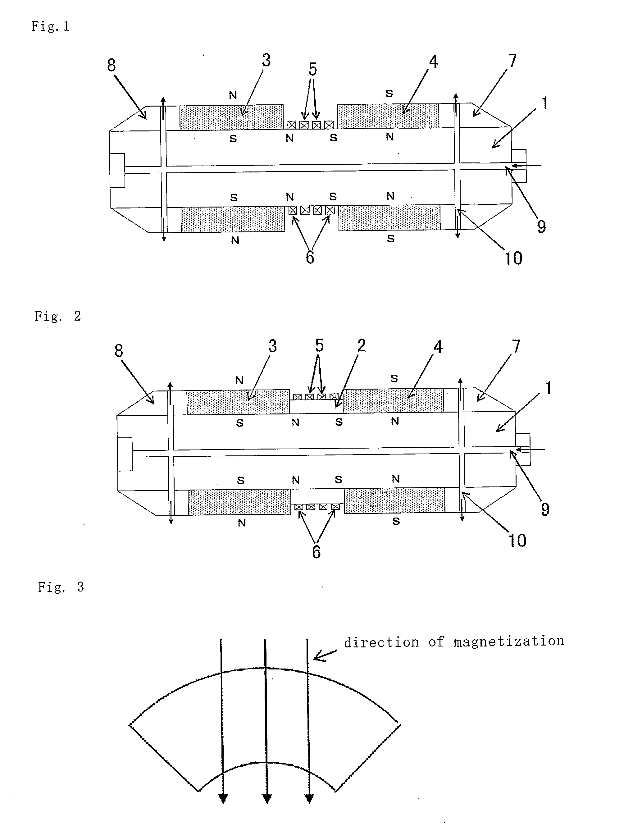
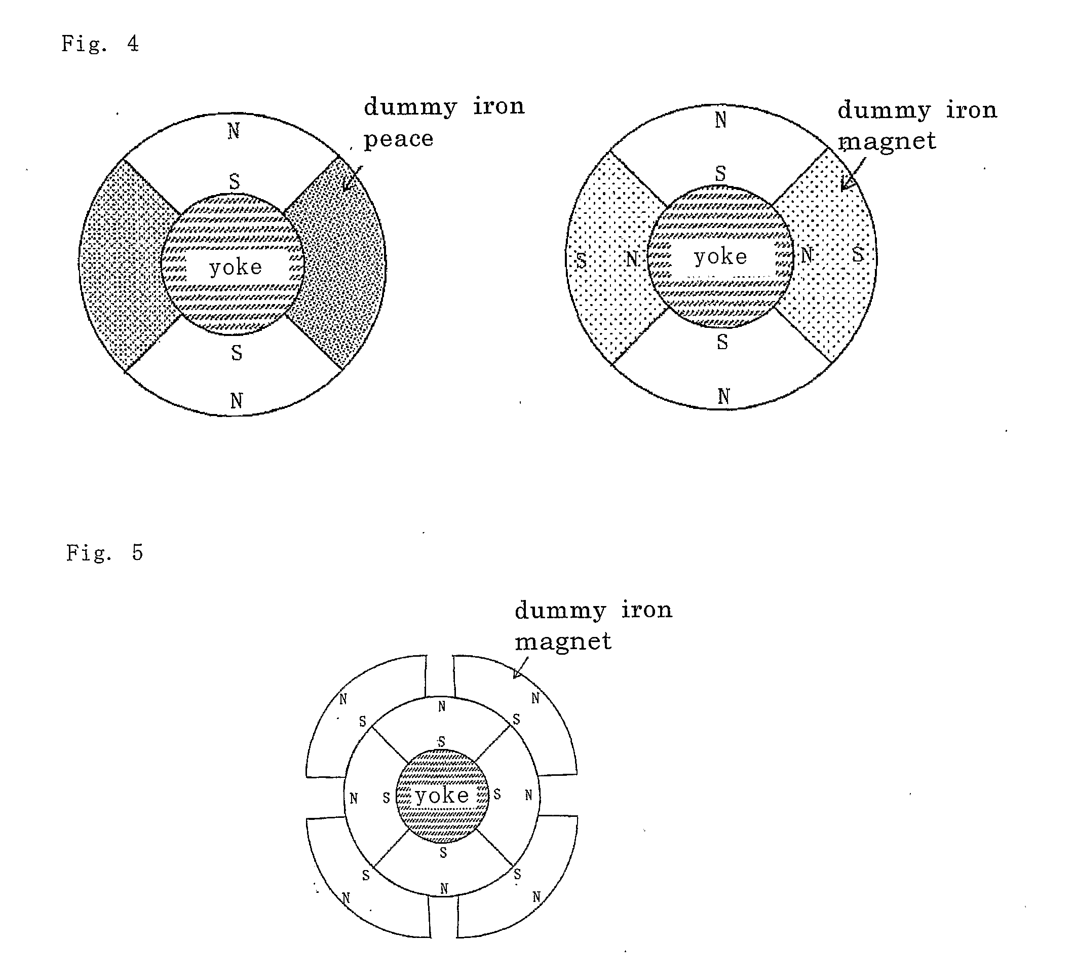
[0011]Through researches into the method of eddy current flaw detection for magnetic tubes, the inventors of the present application found that flaws in magnetic tubes can be detected more accurately by applying eddy current flaw detection using a probe having such a constitution as detection coils are disposed around a central portion of a cylindrical yoke, inner excitation coils are disposed on both sides of the detection coils, and permanent magnets are disposed around the yoke on both sides of the excitation coils so that the directions of magnetization thereof lie in the radial direction of the yoke and magnetic poles on the yoke side are different from each other.
[0017]Through researches into the eddy current flaw detection for magnetic tubes, the inventors of the present application devised another present invention by finding that flaws in magnetic tubes can be detected more accurately by applying eddy current flaw detection method using a probe that has such a constitution as detection coil is disposed around a central portion of a cylindrical yoke and permanent magnets are disposed around the yoke on both sides of the detection coil so that the directions of magnetization lie in the radial direction of the yoke and magnetic poles on the yoke side are different from each other, wherein a permanent magnet is further mounted in the central portion of the probe so that the direction of magnetization lies in axial direction (the direction of the cylindrical axis) of the yoke.
[0019]Through researches into the eddy current flaw detection for magnetic tubes, the inventors of the present application devised yet another present invention by finding that flaws in magnetic tubes can be detected more accurately by applying eddy current flaw detection method to the inside of the magnetic tubes using a probe that has such a constitution as detection coil is disposed around a central portion of a cylindrical yoke and permanent magnets are disposed around the yoke on both sides of the detection coil so that the directions of magnetization lie in the radial direction of the yoke and magnetic poles on the yoke side are different from each other, wherein a permanent magnet is further mounted in the central portion of the probe so that the direction of magnetization lies in axial direction of the yoke, and also that flaws of the magnetic tube in portions of baffle provided in the outside can also be accurately inspected by applying the eddy current flaw detection employing multiple frequency method.
[0021]Use of the probes of the present inventions in eddy current flaw detection of magnetic tubes makes it possible to detect flaws more accurately.

Problems solved by technology

When inspecting a magnetic tube made of carbon steel, ferritic stainless steel, duplex phase stainless steel (or tow-phase stainless steel) consisting of ferrite phase and austenite phase or the like, flaws cannot be detected accurately since the eddy current flaw detection probe for non-magnetic tubes causes eddy currents to flow only in the surface and sensitivity of the detector is adversely affected by a noise attributable to local variation in magnetic permeability.
While use of this probe enables eddy current flaw detection for a weakly magnetic tube such as duplex phase stainless steel tube, it is not sensitive enough to detect small flaws in a ferromagnetic tube made of carbon steel or the like.

Method used


Image

  • Eddy current flaw detection probe
  • Eddy current flaw detection probe
  • Eddy current flaw detection probe

Examples


example 1

[0083]A probe same as that shown in FIG. 2 was fabricated, by using members of the following materials and shapes.

Yoke 1: Annealed carbon steel S15C

Permanent magnet 2: Neodymium magnet manufactured by Asahi Corporation

[0084]Ring shape measuring 25.5 mm in outer diameter, 21 mm in inner diameter and 6.4 mm in length

Permanent magnets 3, 4: Neodymium magnets manufactured by Asahi Corporation

[0085]Ring shape measuring 28 mm in outer diameter, 21 mm in inner diameter and 30 mm in length divided into four parts

Detection coils 5, inner excitation coils 6: Formed from a copper wire having a diameter of 0.08 mm wound 70 turns into size of 1.0 mm in width and 1.0 mm in depth, with separation of 0.8 mm between coils.

Guides 7, 8: Polyacetal (copolymer) DURACON (trademark) manufactured by Polyplastics Co., Ltd., 28.4 mm in outer diameter

Adhesive to bond the permanent magnets to the yoke: Acrylic adhesive Hardlock (trademark) manufactured by DENKI KAGAKU KOKGYO KABUSHIKI KAISHA

[0086]The magnetic ...

example 2

[0093]The air intake hole 4 mm in diameter was formed inside in the axial direction of the yoke (direction of the cylindrical axis of the yoke) and eight air discharge holes 2 mm in diameter were formed to extend in the radial direction from the air intake hole on both sides (guide sections) of the permanent magnets of the probe used in Example 1.

[0094]Air was supplied through the air intake hole at a pressure controlled by a regulator and the probe was pulled so as to move at a constant speed while discharging air through the air discharge holes with a spring balance attached to an end of the probe that was inserted into the same ferromagnetic tube as that of Example 1, and the pulling force immediately before the probe started to move was measured. Measurement was made five times under the same condition, and the measurements were averaged.

[0095]Results of the measurements are shown in Table 1. It is indicated that the pulling force decreased and scanning became easier, when the a...

example 3

[0097]Artificial flaws were given to a ferromagnetic tube (carbon steel STB340 measuring 34 mm in outer diameter, 2.3 mm in thickness and 900 mm in length) by forming a through hole of diameter 1 mm, a rectangular groove measuring 5 mm in width, 12.5 mm in length and 25% of the tube thickness in depth on the outer surface, a rectangular groove measuring 5 mm in width, 17.5 mm in length and 50% of the tube thickness in depth on the outer surface, an inner circumferential groove measuring 1.5 mm in width and 20% of the tube thickness in depth, an inner circumferential groove measuring 1.5 mm in width and 70% of the tube thickness in depth, an outer circumferential groove measuring 1.5 mm in width and 50% of the tube thickness in depth and an outer circumferential groove measuring 1.5 mm in width and 80% of the tube thickness in depth.

[0098]The ferromagnetic tube was inserted into a hole of a dummy baffle (carbon steel SS400, 100 mm in length, 100 mm in width and 15 mm in thickness wit...


PUM


Abstract

An insertion type eddy current flaw detection probe that is capable of more accurately detecting flaws in magnetic tubes is provided. A method for inspecting magnetic tubes for flaws with high accuracy is also provided. A eddy current flaw detection probe comprises a cylindrical yoke (1), a plurality of detection coils (5) disposed around the central portion of the cylindrical yoke in the direction of a cylindrical axis thereof, first and second inner excitation coils (6) disposed on both sides of the plurality of detection coils in the direction of the cylindrical axis, and first and second permanent magnets (3, 4) disposed around the yoke on both sides of the first and second excitation coils in the direction of the cylindrical axis so that the direction of magnetizations thereof are parallel to the radial direction of the yoke and magnetic poles on the cylindrical yoke side thereof are different from each other.

Description

TECHNICAL FIELD[0001]The present invention relates to an eddy current flaw detection probe, and in particular to an insertion type eddy current flaw detection probe suitable for detecting flaws in magnetic tubes.[0002]The present invention also relates to a method for inspecting magnetic tubes for flaw with high accuracy.BACKGROUND ART[0003]Among methods for inspecting metallic materials is the eddy current flaw detection. The eddy current flaw detection by means of the insertion type eddy current flaw detection probe is widely employed in the inspection of non-magnetic tubes made of such metals as austenitic stainless steel, titanium or copper alloy.[0004]When inspecting a magnetic tube made of carbon steel, ferritic stainless steel, duplex phase stainless steel (or tow-phase stainless steel) consisting of ferrite phase and austenite phase or the like, flaws cannot be detected accurately since the eddy current flaw detection probe for non-magnetic tubes causes eddy currents to flow...

Claims


Application Information

Patent Timeline
IPC IPC(8): G01N27/82
CPCG01N27/904G01N27/9033G01N27/902G01N27/9006G01R33/02
Inventor HASHIMOTO, MITSUOMORI, HISAKAZUSUETSUGU, HIDEHIKOTADA, TOYOKAZU
Owner SUMITOMO CHEM CO LTD
Learn More