Reference frequency generating device

a frequency generation and reference technology, applied in the direction of electrical equipment, pulse automatic control, etc., can solve the problems of difficult size reduction and limited accurate estimation of characteristic, and achieve the effect of high precision, high precision and high precision

Inactive Publication Date: 2012-01-12
FURUNO ELECTRIC CO LTD
View PDF9 Cites 9 Cited by
  • Summary
  • Abstract
  • Description
  • Claims
  • Application Information

AI Technical Summary

Benefits of technology

[0009]The problem to be solved by the present invention is like the above, and means for solving the problem and its effect are described below.
[0010]According to the aspect of the present invention, a reference frequency generating device having the following configurations is provided. That is, the reference frequency generating device includes a synchronizing circuit, a detector, a memory unit, and a controller. The synchronizing circuit controls a digitally controlled oscillator with a first control signal acquired based on a reference signal. The detector detects an environmental value indicative of an environment where the digitally controlled oscillator is used. The memory unit can store a correspondence relation between a control value of the first control signal and the environmental value when the first control signal is determined. The controller determines a second control signal based on the environmental value detected by the detector and the correspondence relation stored in the memory unit when the reference signal cannot be acquired, and controls the digitally controlled oscillator.
[0011]Thereby, while the reference signal is acquirable, the digitally controlled oscillator is controllable with the first control signal of the synchronizing circuit with high precision. On the other hand, even if it becomes impossible to acquire the reference signal, the controller can control the digitally controlled oscillator with high precision based on the second control signal. Moreover, since the digitally controlled oscillator can be constructed from semiconductor(s), their usable temperature ranges are wide and it can have a configuration which is strong against a shock and vibration. Furthermore, even if time passes, the device can have a configuration where characteristics of the digitally controlled oscillator are hard to change.
[0012]In the reference frequency generating device, it may be preferred that the correspondence relation stored in the memory unit is obtained in a state where the reference signal is synchronized with the signal outputted from the digitally controlled oscillator by the synchronizing circuit.
[0013]Thereby, since the correspondence relation can be obtained with high precision, when it becomes impossible to acquire the reference signal, the digitally controlled oscillator can be controlled with better accuracy.
[0014]In the reference frequency generating device, it may be preferred that the digitally controlled oscillator includes a delay element.

Problems solved by technology

As described above, the F-V characteristic of the voltage controlled oscillator using the crystal oscillator changes with time and, therefore, an accurate estimation of the characteristic is limited.
Furthermore, it is hard to say that the voltage controlled oscillator provided with the crystal oscillator has a usable temperature range which is wide enough (even if it is the isothermal-bath type) and, therefore, a configuration which can be used also in a severer environment has been demanded.
The voltage controlled oscillator with the isothermal bath is also required for improvements against that it is expensive, it is difficult to be reduced in size, etc.

Method used


Image

  • Reference frequency generating device
  • Reference frequency generating device
  • Reference frequency generating device

Examples


Embodiment Construction

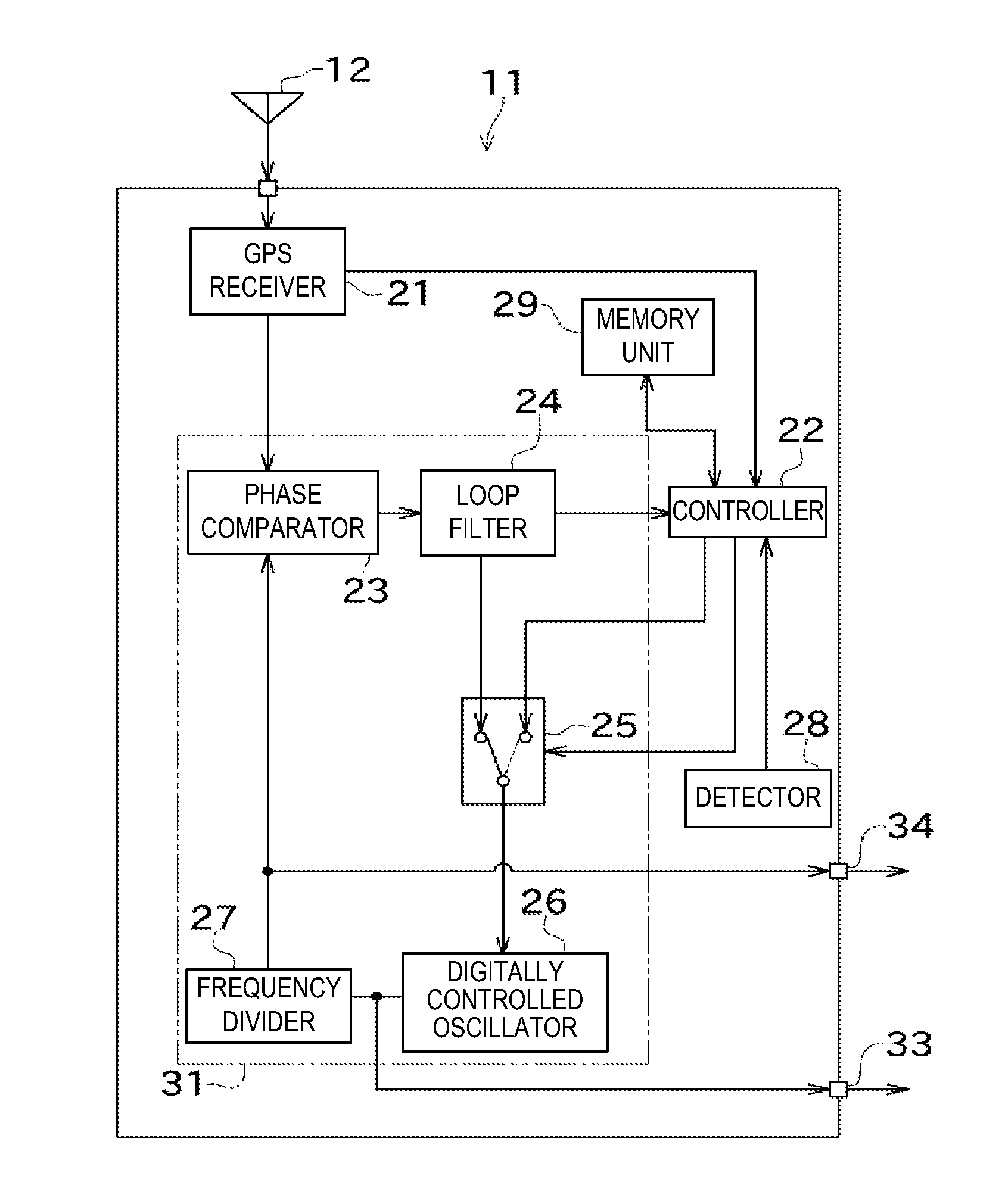
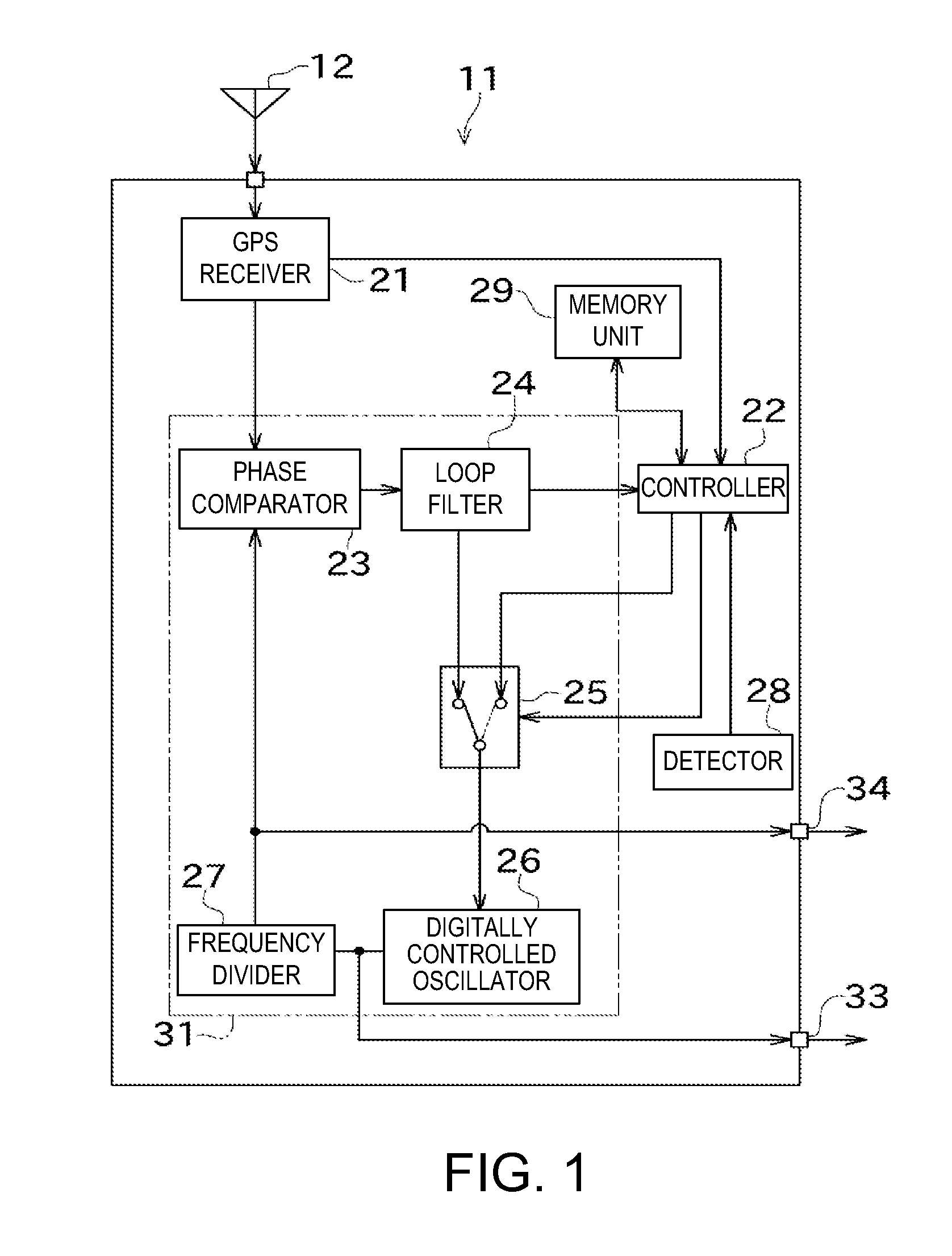
[0038]Next, one embodiment of the present invention is described with reference to the drawings. FIG. 1 is a block diagram schematically showing a reference frequency generating device 11 of this embodiment. FIG. 2 is a particular circuit diagram of a digitally controlled oscillator 26 of this embodiment. FIG. 3 is a particular circuit diagram of a phase comparator 23 of this embodiment. FIG. 4 is a diagram conceptually illustrating a method of measuring phase differences using phase comparison delay elements 52 of the phase comparator 23 of this embodiment.

[0039]The reference frequency generating device 11 of this embodiment is used for base stations of a cellular phone system, transmitting stations of ground digital broadcasting, WiMAX (Worldwide Interoperability for Microwave Access) communication equipment, etc. This reference frequency generating device 11 functions as a master clock generator, and provides reference frequency signals to certain user side apparatuses connected ...


PUM


Abstract

The disclosed is a reference frequency generating device (11), which includes a GPS receiver (21), a PLL circuit (31), a detector (28), a memory unit (29), and a controller (22). The PLL circuit (31) controls the digitally controlled oscillator (26) based on a synchronizing control signal acquired based on a reference signal from the GPS receiver (21). The memory unit (29) stores a correspondence relation between a control value of the synchronizing control signal, and a voltage value and a temperature at that time. When the reference signal is not acquired, the controller 22 determines a holdover control signal based on the correspondence relation, and the voltage and temperature detected by the detector 28, and controls the digitally controlled oscillator (26).

Description

TECHNICAL FIELD[0001]The current invention relates to a reference frequency generating device.RELATED ART[0002]Conventionally, voltage controlled oscillators have been known as oscillators which can change a frequency of an output signal. The voltage controlled oscillator is an oscillator which can change an output frequency according to a control voltage inputted, for example, and what is constructed using a crystal oscillator (Voltage Controlled Crystal Osillator, VCXO) is known. Generally, in this voltage controlled oscillator, a control voltage pair oscillating frequency characteristic (hereinafter, referred to as an “F-V characteristic”) changes with a change of temperature. Therefore, an isothermal-bath type voltage controlled oscillator, having a configuration such that it has a crystal oscillator built in an isothermal bath to keep the temperature constant, has also been developed.[0003]In this voltage controlled oscillator, since the F-V characteristic changes according to ...

Claims


Application Information

Patent Timeline
Patent Type & Authority Applications(United States)
IPC IPC(8): H03L7/00
CPCH03L7/0996H03L2207/50H03L7/14H03L7/085
Inventor MIYAHARA, KAZUNORI
Owner FURUNO ELECTRIC CO LTD
Why Eureka
Try Eureka