Non-contact control method and device

a non-contact control and control method technology, applied in the direction of anti-theft devices, program control, instruments, etc., can solve the problems of non-contact latch tools that vehicle doors are and non-contact latch tools cannot be easily damaged by external force and opened. , to achieve the effect of reducing the probability of being pirated, saving power consumption, and improving use security

Inactive Publication Date: 2012-01-12
DEUTRON ELECTRONICS CORP
View PDF3 Cites 44 Cited by
  • Summary
  • Abstract
  • Description
  • Claims
  • Application Information

AI Technical Summary

Benefits of technology

[0009]Accordingly, the present invention is a non-contact control device, which has advantages of being power-saving and having high security.
[0012]In view of the above, in the non-contact control device and the non-contact control method according to the present invention, the master control module actively turns on the slave control module, such that the slave control module is maintained at a sleep and power-saving mode usually, so as to save power consumption. Furthermore, the RFID receiver firstly identifies whether the low-frequency start signal is correct, and the first Bluetooth transceiver also identifies an encrypted signal. That is to say, the non-contact control device and the non-contact control method require double identification, so as to reduce probability of being pirated, thereby further improving security in use.

Problems solved by technology

However, concave-convex engraved patterns of the mechanical keys are easily copied, and the vehicle doors are easily damaged by external force and opened.
Therefore, doubts about the security of the mechanical keys and latch tools are raised to a considerable degree.
Although the non-contact latch tool cannot be easily damaged by the external force and opened, during an identification code transmission process performed by the RFID tag and the RFID Reader, the identification code still may be pirated.
Therefore, the non-contact key still has the risk of being cracked.
However, if a Bluetooth transmitter is arranged on the non-contact key, power consumption required by the Bluetooth transmitter is much higher than the RFID tag.
On the contrary, the security of the Bluetooth is much higher than the RFID, but the power consumption is also much higher than RFID.

Method used


Image

  • Non-contact control method and device
  • Non-contact control method and device
  • Non-contact control method and device

Examples


first embodiment

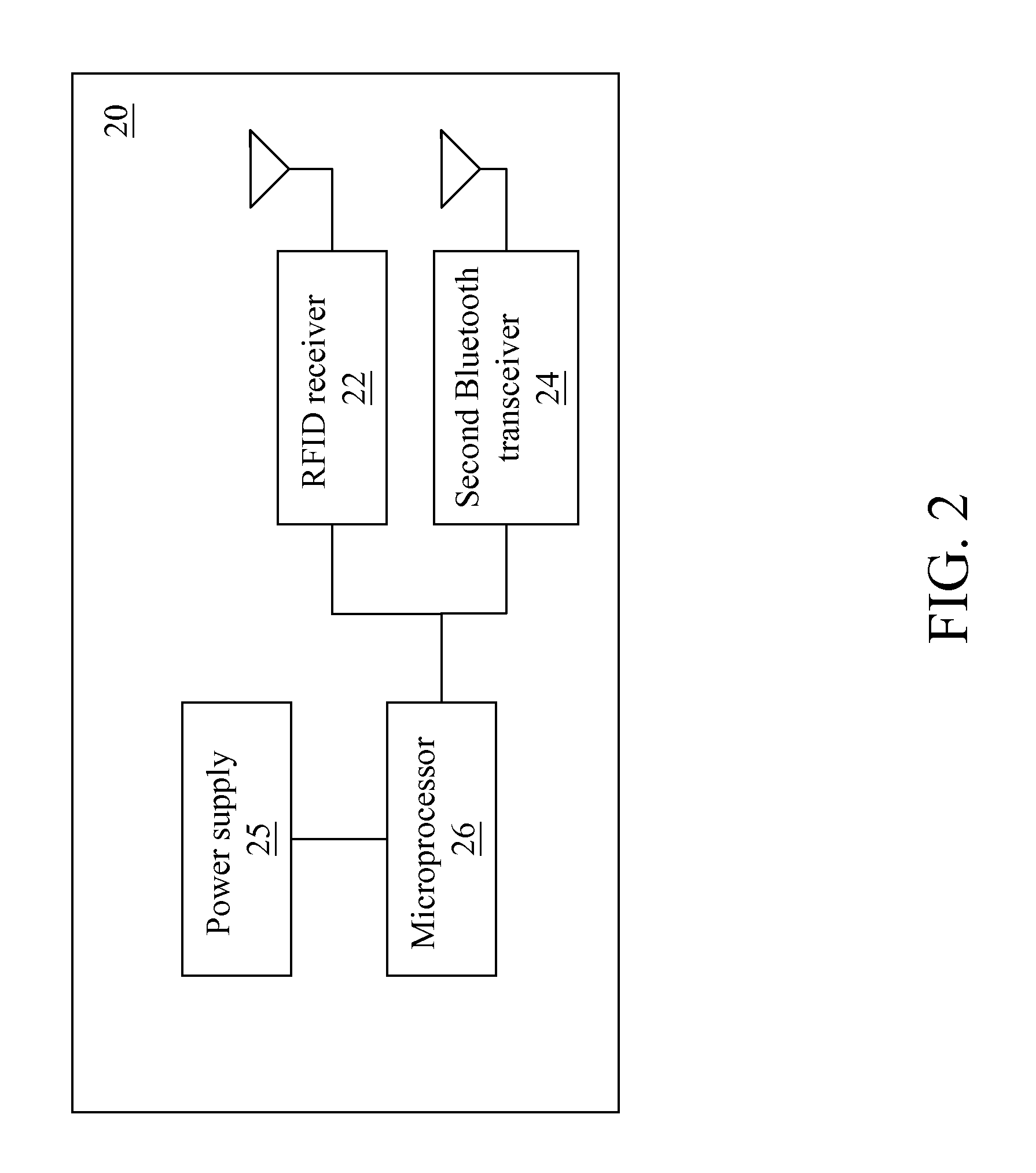
[0027]FIG. 2 is a system block diagram of a slave control module. Referring to FIG. 2, the slave control module 20 comprises an RFID receiver 22 (a second RFID component), a second Bluetooth transceiver 24 (a second Bluetooth component), and a second microprocessor 26.

[0028]The slave control module 20 is disposed in a non-contact key, and is used to interact with a master control module 10.

[0029]Power of the slave control module 20 is supplied by a power supply 25. The power supply 25 is powered by a common battery, and the power is converted by a direct current (DC) / DC and then is supplied to the slave control module 20.

[0030]The RFID receiver 22 is an RFID tag. The second Bluetooth transceiver 24 is a wireless transmission element satisfying Bluetooth communication specifications. The RFID receiver 22, the second Bluetooth transceiver 24, and the second microprocessor 26 can be integrated into an SOC IC, or each is an individual IC.

[0031]The second microprocessor 26 is electricall...

second embodiment

[0033]FIG. 3 is a system block diagram of a slave control module. Referring to FIG. 3, the slave control module 20 comprises an RFID receiver 22, a second Bluetooth transceiver 24, a second microprocessor 26, a power supply 25, and a key 28.

[0034]In this embodiment, in a state that a user is allowed to start a vehicle, after the user presses down the key 28, the slave control module 20 controls the master control module 10 to operate in a pairable mode. In the pairable mode, the first Bluetooth transceiver 14 of the master control module 10 is paired with a device with another Bluetooth transceiver. After being paired, the device with another Bluetooth transceiver has an unlocking authority and serves as a backup key. The device with the Bluetooth transceiver is, for example, a mobile phone or a personal digital assistant (PDA).

third embodiment

[0035]FIG. 4 is a system block diagram of a slave control module. Referring to FIG. 4, the slave control module 20 comprises an RFID receiver 22, and second Bluetooth transceiver 24, a second microprocessor 26, a power supply 25, a key 28, and an indicating lamp 29.

[0036]Furthermore, the slave control module 20 reads a pairing parameter. The pairing parameter comprises, for example, (1) whether another Bluetooth transceiver requires inputting a password; (2) a quantity and a priority of another Bluetooth transceiver capable of being paired; (3) whether vehicle information is allowed to be transmitted to another Bluetooth transceiver.

[0037]When the second microprocessor 26 detects that a voltage supplied by the power supply 25 is lower than a critical value, the indicating lamp 29 continuously flickers, so as to remind the user to replace the battery.

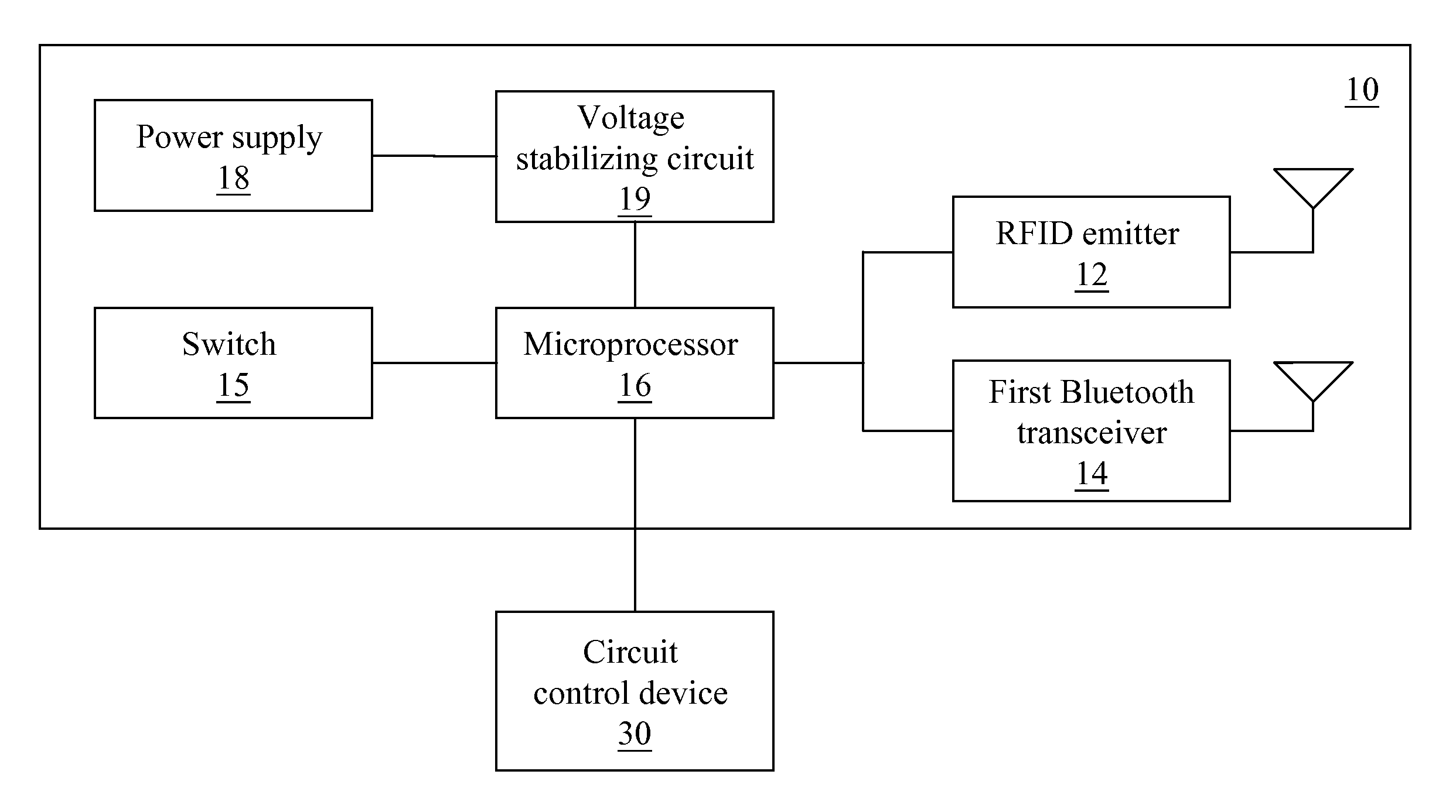
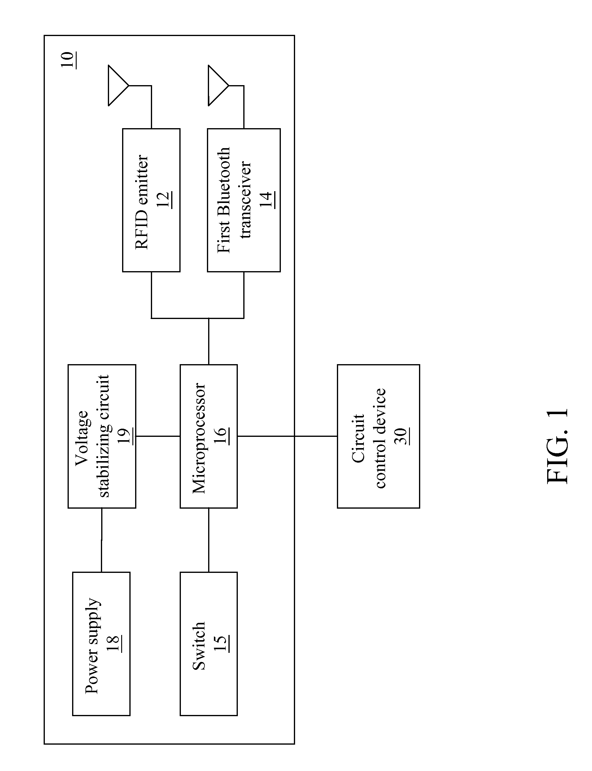
[0038]FIGS. 1 to 4 illustrate hardware architectures of the master control module 10 and the slave control module 20. For the detailed ...


PUM


Abstract

A non-contact control method and a non-contact control device are applied to a lock control device in a non-contact mode for manipulation. The non-contact control device includes a master control module and a slave control module. Both the master control module and the slave control module include a radio frequency identify (RFID) component and a Bluetooth component. In the master control module and the slave control module, the RFID component serves as first-layer authentication and unlocking and starts the Bluetooth component, and the Bluetooth component serves as second-layer authentication and unlocking and triggers a circuit control device. The master control module actively starts the slave control module and performs pairing and unlocking, so as to achieve a non-contact locking and control mode with low energy consumption and high security.

Description

BACKGROUND OF THE INVENTION[0001]1. Field of the Invention[0002]The present invention relates to a non-contact control method and a non-contact control device, and more particularly to a non-contact control method and a non-contact control device integrating RFID and Bluetooth transmission mechanisms.[0003]2. Related Art[0004]Conventionally, vehicle keys are mechanical keys for opening vehicle doors or starting vehicles. However, concave-convex engraved patterns of the mechanical keys are easily copied, and the vehicle doors are easily damaged by external force and opened. Therefore, doubts about the security of the mechanical keys and latch tools are raised to a considerable degree.[0005]Accordingly, a non-contact key (keyless) is developed. Generally, the non-contact key adopts radio frequency identify (RFID) as a technology of sending and receiving signals. An RFID Reader is arranged on the vehicle for reading data of an RFID tag on the key. The RFID tag stores a unique identific...

Claims


Application Information

Patent Timeline
Patent Type & Authority Applications(United States)
IPC IPC(8): G05B19/00
CPCB60R25/243B60R2325/105B60R2325/101
Inventor TUNG, CHIA CHUN
Owner DEUTRON ELECTRONICS CORP
Why Eureka
Try Eureka