Magnetic transfer master substrate, magnetic transfer method using the substrate, and magnetic transfer medium

Inactive Publication Date: 2012-01-12
FUJI ELECTRIC CO LTD
View PDF3 Cites 15 Cited by
  • Summary
  • Abstract
  • Description
  • Claims
  • Application Information

AI Technical Summary

Benefits of technology

[0019]The invention provides a master substrate, and a manufacturing method thereof, that improve durability and magnetic transfer performance in the manufacture of

Problems solved by technology

As it is generally often the case when the servo information is recorded using a magnetic head, a problem has occurred in that a write time has increased along with an increase in recording tracks in recent years, and the production efficiency of the HDD has dropped.
In this kind of situation, with the kinds of structure of the master substrates disclosed in the heretofore known Japanese Patent No. 3,343,343 and Japanese Patent No. 3,329,259 wherein the surface of the ferromagnetic bod

Method used


Image

  • Magnetic transfer master substrate, magnetic transfer method using the substrate, and magnetic transfer medium
  • Magnetic transfer master substrate, magnetic transfer method using the substrate, and magnetic transfer medium
  • Magnetic transfer master substrate, magnetic transfer method using the substrate, and magnetic transfer medium

Examples


example 1

[0058]Master Substrate Fabrication

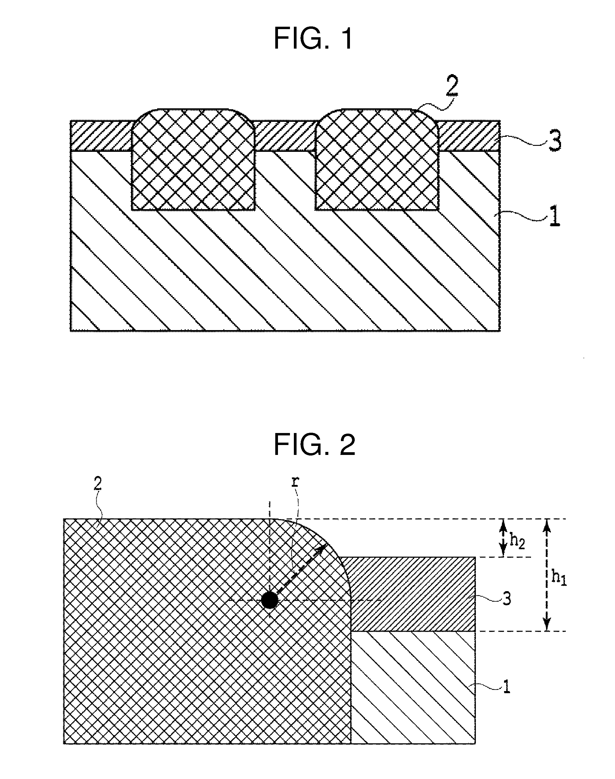
[0059]The magnetic transfer master substrate of the invention is fabricated using the configuration shown in FIG. 1.

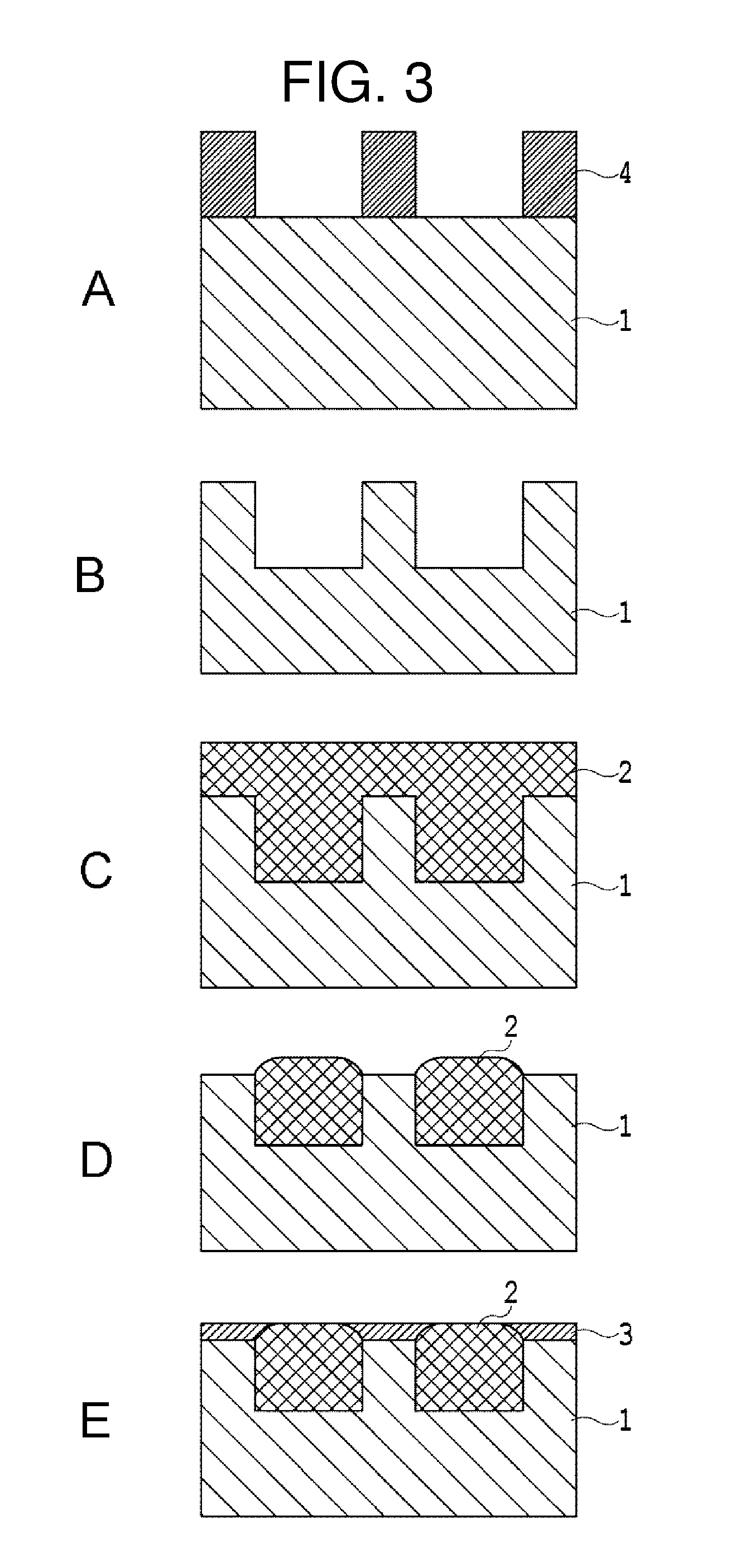
[0060]Firstly, a Si substrate of outer diameter 65 mm, inner diameter 20 mm, and thickness 0.635 mm is prepared, and a carbon film is deposited to a thickness of 80 nm using a sputtering method. The carbon film is pattern-processed in a subsequent step, becoming one portion of the non-magnetic base.

[0061]Next, an SOG resist is applied to a thickness of 70 nm using a spin coating method. A commercially available Tokyo Ohka Kogyo Co., Ltd. OCNL505 is used as the SOG.

[0062]Subsequently, an imprinting is carried out using a Ni stamper on which is formed a pattern corresponding to information to be transferred, forming an irregular pattern corresponding to the transfer pattern on the surface of the SOG. The pattern forming imprinting is carried out by superimposing the Ni stamper on the resist surface of the substrate, carrying out a 100 MP...

example 2

[0071]Fabrication of Samples Having Various Cross-Sectional Forms

[0072]Various master substrates are fabricated, changing only the RIE conditions in the Example 1. In the example, by adopting RIE conditions of RIE power 100 to 200 W, substrate bias 10 to 50 W, O2 gas flow rate with respect to Ar gas 100 10 to 50, degree of vacuum 0.1 to 1.5 Pa, and processing time 100 to 400 seconds, various kinds of master substrate are fabricated wherein the height of the ferromagnetic body material protruding above the surface of the non-magnetic base is 1.0 to 16.0 nm, and the radius of curvature of the corner portion of the protruding ferromagnetic body is 1.0 to 15.0 nm.

[0073]Subsequently, the non-magnetic protective film 3 is formed on each sample, using a fabricating method the equivalent of that in the Example 1. The amount of SOG dilution and spin coating number of rotations are adjusted in accordance with the height h1 of the ferromagnetic body 2, and an application of the SOG is carried ...

example 3

[0074]Magnetic Transfer Test

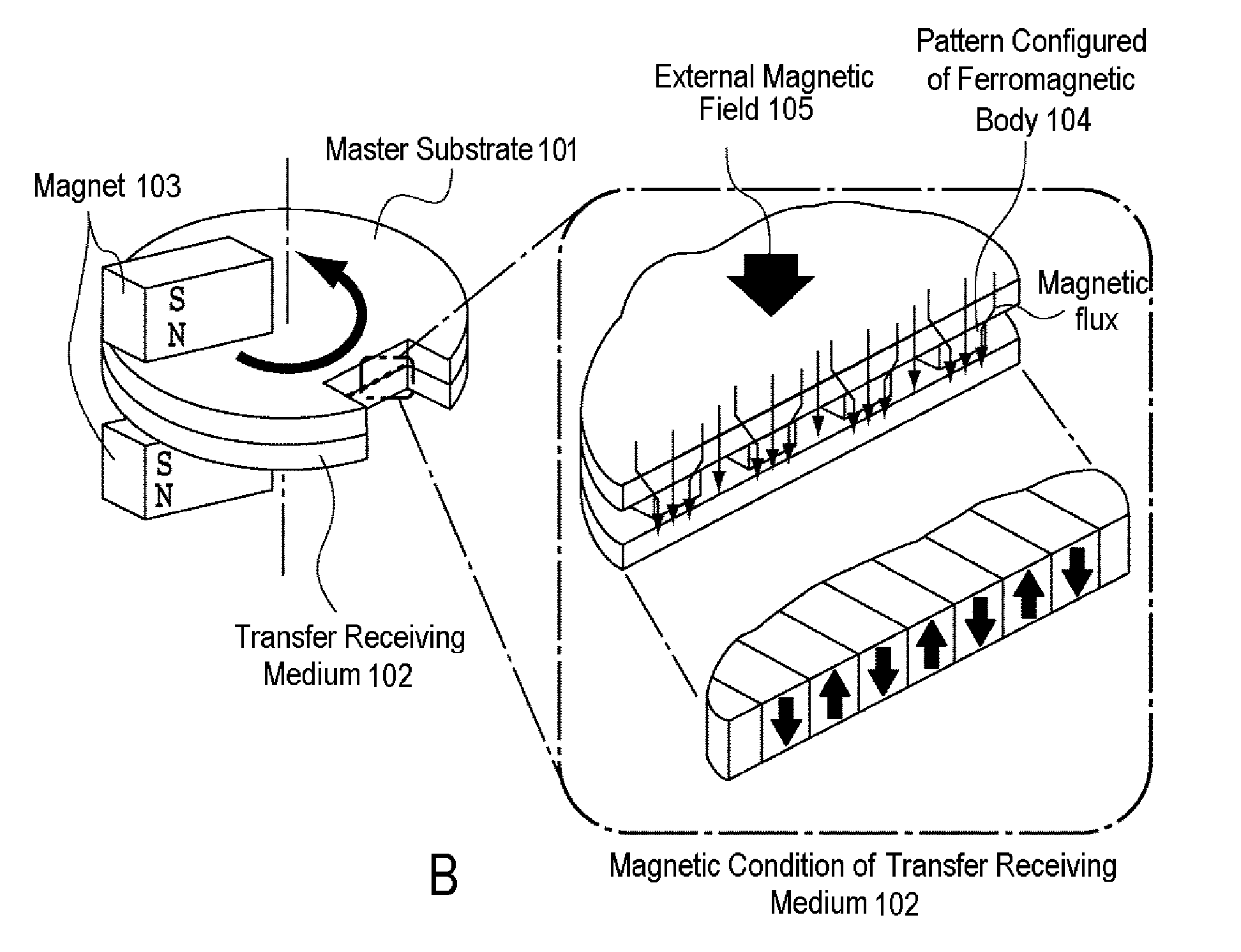
[0075]A magnetic transfer of servo information to the magnetic recording medium is carried out using the master substrates fabricated in Examples 1 and 2. Furthermore, in order to investigate the repetition durability of the master substrate during the magnetic transfer, the magnetic transfer is carried out repeatedly while replacing the transfer receiving medium. During the repetition, cleaning of the surface is carried out by wiping the surface of the master substrate with a tape every 1,000 times.

[0076]Servo Characteristic Evaluation

[0077]An evaluation of the servo characteristics on the magnetic recording media onto which the magnetic transfer is carried out using the heretofore described method is carried out for the first, fifty thousandth, and one hundred thousandth magnetic recording media among the repetitions.

[0078]For the evaluation of the servo characteristics, a drive test is carried out using an evaluation drive. An evaluation of the possibi...


PUM

PropertyMeasurementUnit
Pressureaaaaaaaaaa
Radiusaaaaaaaaaa
Radiusaaaaaaaaaa

Abstract

A magnetic transfer master substrate includes a non-magnetic base having depressed portions formed on a surface thereof corresponding to an information signal array, a ferromagnetic body formed in the depressed portions and having a top portion thereof protruding above the surface of the non-magnetic base, and a non-magnetic protective film covering the surface of the non-magnetic base, except for the depressed portion thereof, and also covering a side portion of the ferromagnetic body. A section through the ferromagnetic body, taken perpendicularly to the substrate, includes a round corner, a curvature of which has a radius of no less than 1 nm and no more than 10 nm. The apex of the top portion of the ferromagnetic body protrudes above the surface of the non-magnetic base by 2 nm or more, and protrudes above the surface of the non-magnetic protective film by a distance less than the radius of the curvature.

Description

BACKGROUND OF THE INVENTION[0001]1. Technical Field[0002]The present invention relates to a magnetic recording medium. More particularly, the magnetic recording medium of the invention relates to a magnetic recording medium wherein there is no need to separately write servo information. Also, the invention includes a magnetic recording medium manufacturing method whereby servo information can be easily recorded.[0003]2. Related Art[0004]In a general HDD device, ahead is caused to hover around 10 nm above a magnetic recording medium, and a data read / write is carried out. Bit information on the magnetic recording medium is stored in concentrically disposed data tracks. The magnetic head is positioned above the data tracks when reading or writing data. Servo data for the positioning is recorded at constant angle intervals with respect to the data tracks on the magnetic recording medium. As it is generally often the case when the servo information is recorded using a magnetic head, a pr...

Claims


Application Information

Patent Timeline
IPC IPC(8): G11B5/86C23F1/00
CPCB82Y10/00C23F4/00G11B5/865G11B5/855G11B5/743
Inventor UCHIDA, SHINJI
Owner FUJI ELECTRIC CO LTD
Why Eureka
Try Eureka