Driver for driving power switch element

Active Publication Date: 2012-01-12
DELTA ELECTRONICS INC
View PDF5 Cites 41 Cited by
  • Summary
  • Abstract
  • Description
  • Claims
  • Application Information

AI Technical Summary

Benefits of technology

[0015]The driver and the driving circuit of the invention may balance excitation current so that power consumption resulting from capacitors charging and discharging may be prevented, driving efficiency may be increased and impedance for blocking energy delivery may be decreased. Therefore, rising and falling speed of signals are enhanced. Moreover, the driver and the driving circuit may shorten the width of on-pulses if rising speed of an equ

Problems solved by technology

However, as power density and power efficiency requirements increasingly heighten, especially for low frequencies such frequencies lower than 10 kHz, the size and the power consumption of transformers become more of an issue.
However, there are a lot of drawbacks in the above mentioned prior art.
For example, driving consumption is large.
At the rising edge, the energy stored in the capacitor CY has to be released before a next rising edge in order to sustain operation, which

Method used


Image

  • Driver for driving power switch element
  • Driver for driving power switch element
  • Driver for driving power switch element

Examples


Embodiment Construction

[0051]The following description is of the best-contemplated mode of carrying out the invention. This description is made for the purpose of illustrating the general principles of the invention and should not be taken in a limiting sense. The scope of the invention is best determined by reference to the appended claims.

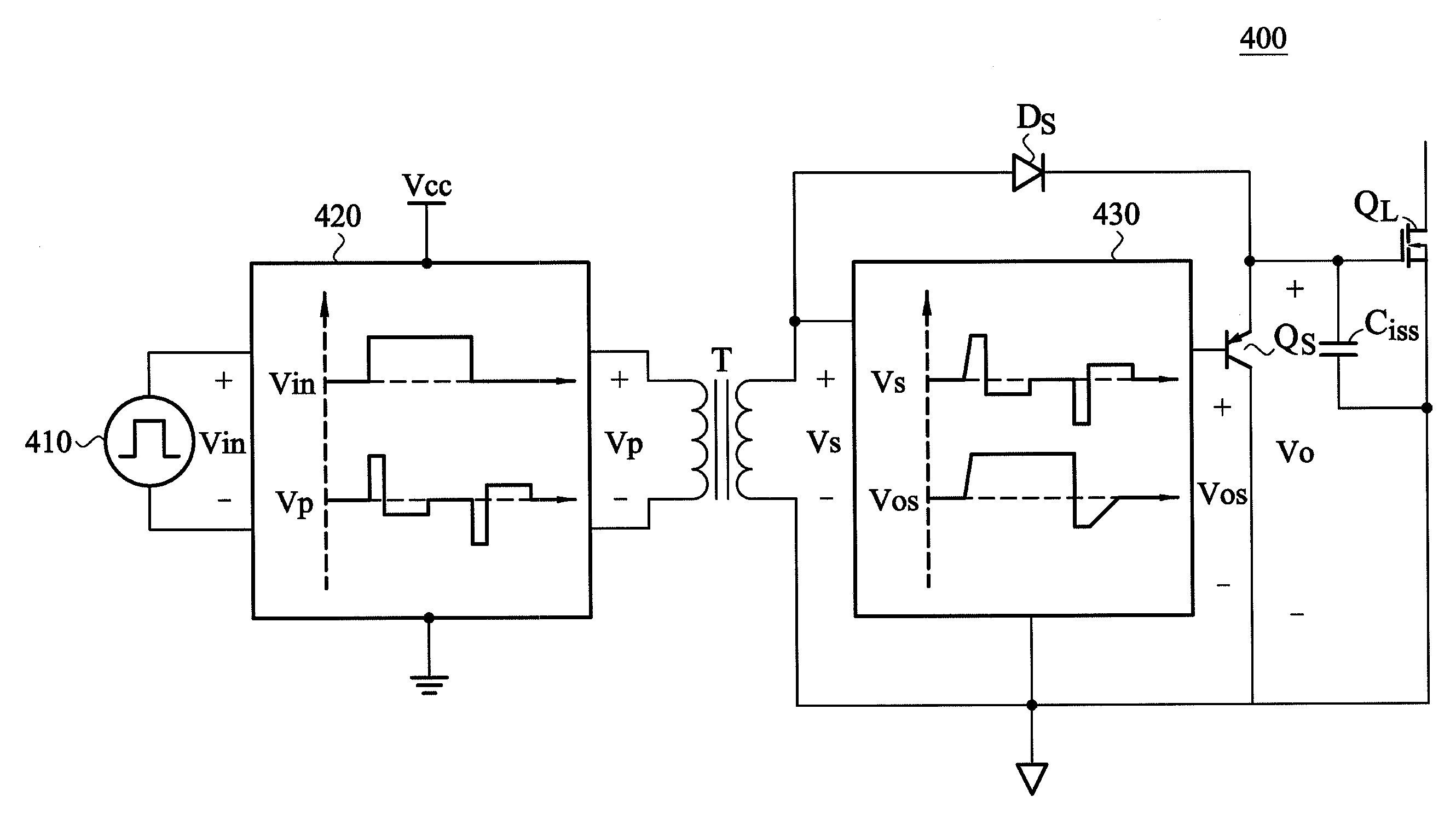
[0052]FIG. 4 is a diagram showing a driver of the invention. The driver 400 includes a signal source 410, a first modulation 420, a transformer T, a second modulation circuit 430, a unidirectional on device Ds and a switch device Qs.

[0053]A signal source 410 provides a square signal, wherein a working frequency and duty cycle thereof may be changed dramatically. For example, the working frequency of the square signal may be a low frequency such as 10 k Hz or a high frequency such as more than 1 MHz, and the duty cycle of the square signal may be smaller than 2% or larger than 98%. The first modulation circuit 420 provides on-pulses according to edges such as rising edg...


PUM


Abstract

A driver for driving a driving element includes: a signal source, for providing a square signal; a first modulation circuit, for providing on-pulses and off-pulses according to edges of the square signal; a transformer for coupling output signals of the first modulation circuit to a secondary winding of the transformer to form coupled signals; a second modulation circuit for providing first operating pulses according to coupled on-pulses of the coupled signals, and providing second operating pulses according to coupled off-pulses of the coupled signals; a switch device for turning off the switch device according to the first operating pulses and turning on the switch device according to the second operating pulses, and when the switch device is turned off, coupled on-pulses charge an equivalent capacitor of the driving element to a first driving potential to turn on the driving element, and when the switch device is turned off, the equivalent capacitor discharges to a second driving potential to turn off the driving element, and the width of the on-pulses is less than 1000 ns.

Description

CROSS REFERENCE TO RELATED APPLICATION[0001]This Application claims priority of China Patent Application No. 201010219644.1, filed on Jul. 7, 2010, the entirety of which is incorporated by reference herein.BACKGROUND OF THE INVENTION[0002]1. Field of the Invention[0003]The present invention relates to a driver and in particular relates to a driver for driving a power switch element.[0004]2. Description of the Related Art[0005]Drivers are necessary for controlling when to turn-off and turn-on power switch elements. For isolation purposes, transformers are used to deliver driving signals to power switch elements such as MOSFET, IGBT etc., as FIG. 1 shows. Transformers only deliver driving energy. Thus, when compared to the size of main circuits, the size of the transformers is relatively smaller. However, as power density and power efficiency requirements increasingly heighten, especially for low frequencies such frequencies lower than 10 kHz, the size and the power consumption of tra...

Claims


Application Information

Patent Timeline
IPC IPC(8): H02M3/335H02M3/22
CPCH03K17/691H03K17/6877
Inventor ZENG, JIAN-HONGJIANG, JIANYE, QIFENGYING, JIAN-PING
Owner DELTA ELECTRONICS INC
Why Eureka
Try Eureka