All-optical data center network

a data center network and all-optical technology, applied in the field of data centers, can solve the problems of large amount of electrical power needed to operate a data center, the scalability of date center networks, and the ubiquity of such data centers, and achieve the effects of reducing equipment costs, reducing electric power, and improving the use of available bandwidth

Inactive Publication Date: 2012-01-12
ADHIKARI PRASANNA
View PDF4 Cites 5 Cited by
  • Summary
  • Abstract
  • Description
  • Claims
  • Application Information

AI Technical Summary

Benefits of technology

[0017]In preferred embodiments all logic communication circuits through the core network are all optical fibers. Preferred embodiments utilize frequency multiplexing and time multiplexing. The present invention creates non-interfering circuits by means of their spectral, spatial and temporal separation from each other. Spectral separation of circuits is achieved by making use of different optical wavelengths (spectrum), spatial separation is achieved by using physically different fiber optic network and temporal separation is achieved by means of controlling data transmission time (time-slots). By combining the three independent mutually orthogonal basis sets of spectral, spatial and temporal components, we achieve a method of creating in a three-dimensional space of the basis set. Advantages of the present invention include a huge reduction in electric power required to operate the data center network and a huge reduction in cost of equipment resulting from better use of available bandwidth.

Problems solved by technology

As new online applications and services grow, the ubiquity, size, complexity and cost of such data centers will continue to grow.
One of the limitations of such data center is the large amount of electrical power needed to operate a data center.
Another limitation of date center networks is their scalability.
As stated in [1], event with today's technologies, achieving oversubscription of 1:1 in a data center with more that a few tens of thousands of servers is very challenging and often cost prohibited.
Such scalability limitation is due to the capacity limitation at the core of today's state of the art data center networks.
The third limitation of modern datacenters is their cost, particularly the cost of the networking equipment that interconnects all the computers in a data center.
Therefore, the total cost of high-end switches needed to build a 20,000 computer data center is roughly about $35 million.
In fact, the cost of the networking equipment of a high performance data center is often more than that of its servers.
One of the limitations of modern data centers emanate from their use of packet switching technologies.
One of the downsides of circuit switches network had been its inefficiency in terms of its utilization.
This results in an inherent inefficiency of circuits if the circuits are not fully utilized by the two parties.
However, a downside of a packet switching network is the amount of the processing that needs to be performed at each stage of the network.
First, the intermediate networking equipment needs to perform significant amount of operation as its makes its decision.
However, the need to make such decision for every packet by every component of networking equipment makes it highly inefficient and unscalable.
However, in a very large data center with as many 20,000 servers, the vast amount of processing seems hardly justified.
What make it even more unjustified is that such processing is performed on every single packet that is transported through the network, even though the end-to-end connectivity is relatively limited.
This amount of processing results in significant amount of power consumptions.
Second, packet-switching operation also means that as packet are transported through the network, they are stored and forwarded at each stage of the network Furthermore, it is always the case that packet forwarding cannot begin until the entire packet is received.
Each storing and forwarding process consumes additional power.
But, more importantly, this requirement for storing before forwarding also imposes inherent latency in the network as packets are forward through the network.
However, if the total demand for bandwidth is more than the underlying bandwidth of the network, packet switched networks can experience congestion, resulting in latency of even data loss that can become unacceptable.
As the level of congestion in packet switching network fluctuates, the latency experienced by data packets also fluctuates significantly.
However for certain application such as data centers, such latencies are highly intolerable.
Furthermore, for highly parallel processing applications, jitter experienced by packets in networks can have highly negative impact on the performance of such systems as delay in on one operation because of packet patency can put on hold completion of many other operations.
However, all successful quality of service deliveries require that the underlying network behave within certain statistical bound, a limitation not too far from what is required for a circuit switched network.
However, in a packet switched network, maintenance of such QoS require significant amount of intelligence and processing although delivery of such QoS cannot always be guaranteed.

Method used


Image

  • All-optical data center network
  • All-optical data center network
  • All-optical data center network

Examples


Embodiment Construction

[0031]In present inventions provide methods and apparatus for data center networks that are based on all optical circuits at the core of each data center network and packet aggregation and mapping at the edge.

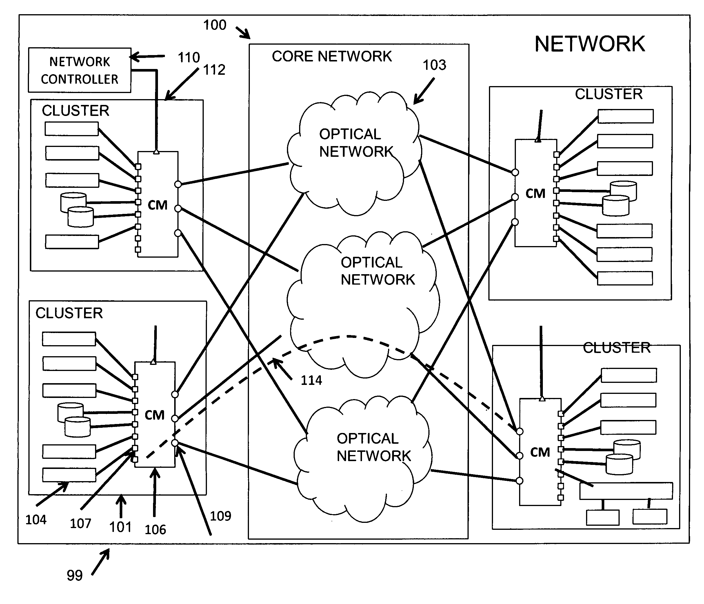
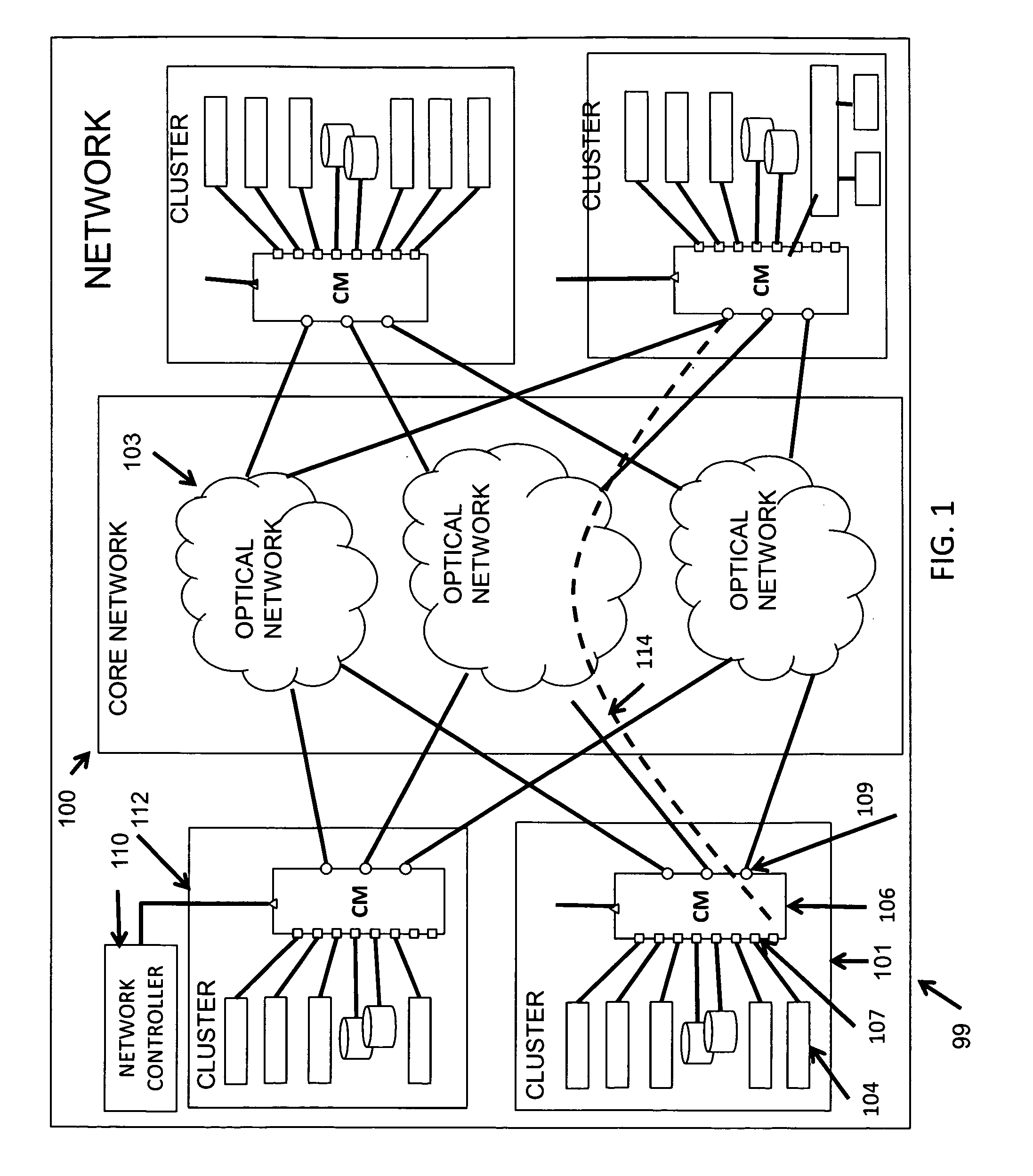
[0032]The high level diagram of a preferred network architecture is described in FIG. 1. It is comprised of a core network 100 interconnecting a number clusters 101. The core network 100 comprises three optical networks 103. A detail description of the preferred core network 100 and optical network 103 is described later in this document. The network also consists of a network controller 110 that is responsible for managing the operation of and monitoring the entire network.

Network Clusters

[0033]A cluster 101 comprises of a set of equipment, including a circuit-module 106. A cluster 101 also comprises of other computing equipment that are typically used in a datacenter, labeled as nodes 104 in FIG. 1. A node may be a server, a network storage device, a switch, a router or any o...


PUM


Abstract

A data center network comprising with an all-optical core network which includes a number of separate all-optical networks to connect clusters of computer network equipment at network nodes. Circuit modules in the data center network each includes a memory bank to provide queues to store information scheduled to be transmitted optically through the all-optical core network. Each circuit module also includes a lambda port module which includes a number of optical mux-demux units and an equal number of lambda ports designed to provide communication between the mux-demux units and the memory bank via a number of optical transceivers. In preferred embodiments all logic communication circuits through the core network are all optical fibers. The present invention creates non-interfering circuits by means of their spectral, spatial and temporal separation from each other.

Description

FIELD OF INVENTION[0001]This invention relates to data networks and in particular to data center networks.BACKGROUND OF THE INVENTION[0002]Behind most online activities engaged in today are large groups of computers closely networked together at facilities commonly referred to as data centers. Whether it is search engines operated by large Internet search engine companies such as Google, online social networking sites such as Facebook or online retailer such as Amazon.com, behind all of their online services are large data centers often consisting of tens of thousands of computers interconnected by means of hundreds of networking components. As new online applications and services grow, the ubiquity, size, complexity and cost of such data centers will continue to grow.[0003]Typical network architecture for data includes of routers and / or switches interconnected in a hierarchical manner using a tree like topology. Computers are typically connected to lower-end switches (edge switches...

Claims


Application Information

Patent Timeline
Patent Type & Authority Applications(United States)
IPC IPC(8): H04B10/20
CPCH04J14/02H04J14/0257H04J14/0286H04J14/0283H04J14/0284H04J14/028
Inventor ADHIKARI, PRASANNA
Owner ADHIKARI PRASANNA
Why Eureka
Try Eureka