Inflatable Life Raft

a life raft and inflatable technology, applied in life-saving, vessel safety, vehicles, etc., can solve the problem of ballooning in the inflation chamber

Inactive Publication Date: 2012-01-12
RAWLINGS LLOYD CONRAD MICHAEL
View PDF13 Cites 5 Cited by
  • Summary
  • Abstract
  • Description
  • Claims
  • Application Information

AI Technical Summary

Benefits of technology

[0004]In accordance with the present invention, there is provided an inflatable life raft comprising: a platform or platform portion formed by two flexible panels joined together by each of a plurality of threads to limit the distance apart that the panels can be moved, the panels being sealed to each other at their edges to form a chamber; detecting means for detecting an indication that the life raft is in the water; and inflating means operable in response to such detection to inflate the chamber with a gas. Preferably, the threads have similar lengths so that, when the chamber is inflated, the panels are substantially parallel. Accordingly, it is possible to fabricate an inflatable life raft which does not balloon out and which can provide a substantially flat platform.
[0007]Further ropes or rope portions are attached to the platform. The rope portions are preferably portions of a continuous rope, the continuous rope including an electroluminescent filament, and the life raft further including means operable in response to the detecting means for activating the electroluminescent filament. This increases the visibility of the rope in the dark to somebody attempting to climb aboard the life raft and also increases the visibility in the dark to a rescuer of the life raft as a whole. The life raft is preferably devoid of a gunwale of like feature which would impede climbing aboard the life raft. The life raft, when inflated, is preferably operable as a life raft either way up.
[0008]The platform may have an opening therethrough at or adjacent the center of the platform. In this case, the detecting means, the inflating means and / or a control unit for the life raft is / are disposed in the opening. A removable cover may be provided for each end of the opening. Depending on which way up the life raft has landed, one cover may be removed to gain access to the central opening, whilst the other cover may be left in place to reduce the amount of water splashing up through the opening.

Problems solved by technology

However, a problem is that, when inflated, the inflation chamber tends to balloon out.

Method used


Image

  • Inflatable Life Raft
  • Inflatable Life Raft
  • Inflatable Life Raft

Examples


Embodiment Construction

[0018]The present invention may be described herein in terms of various functional components and various processing steps. It should be appreciated that such functional components may be realized by any number of hardware or structural components configured to perform the specified functions.

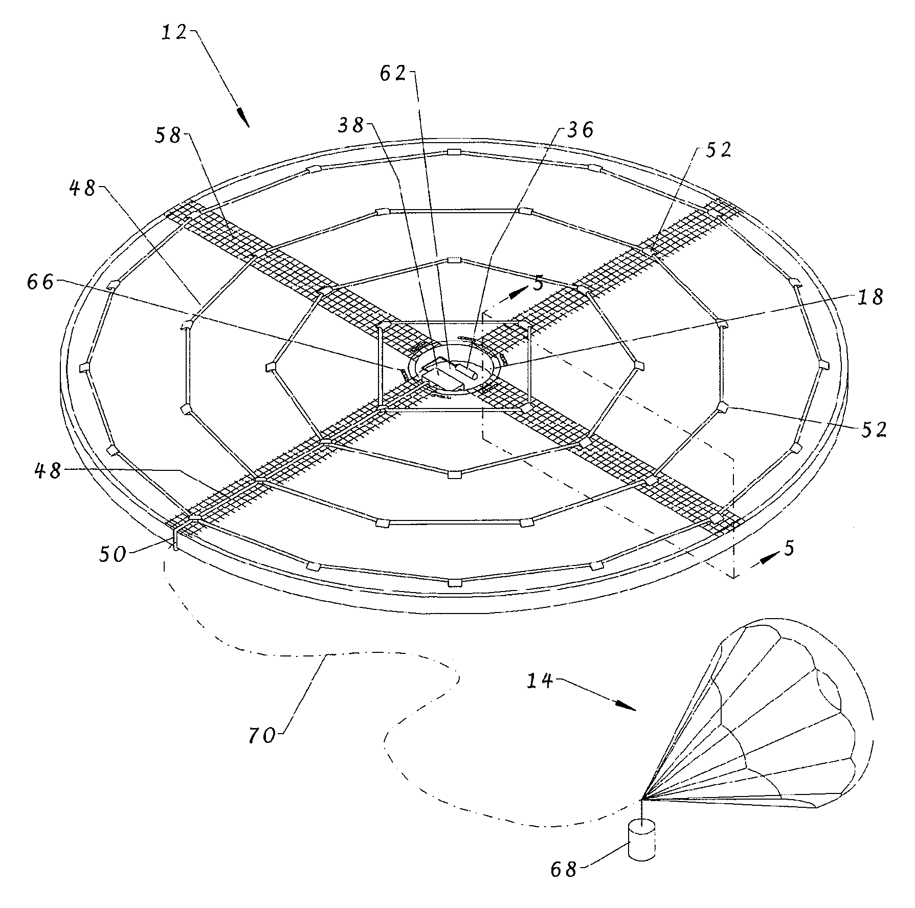
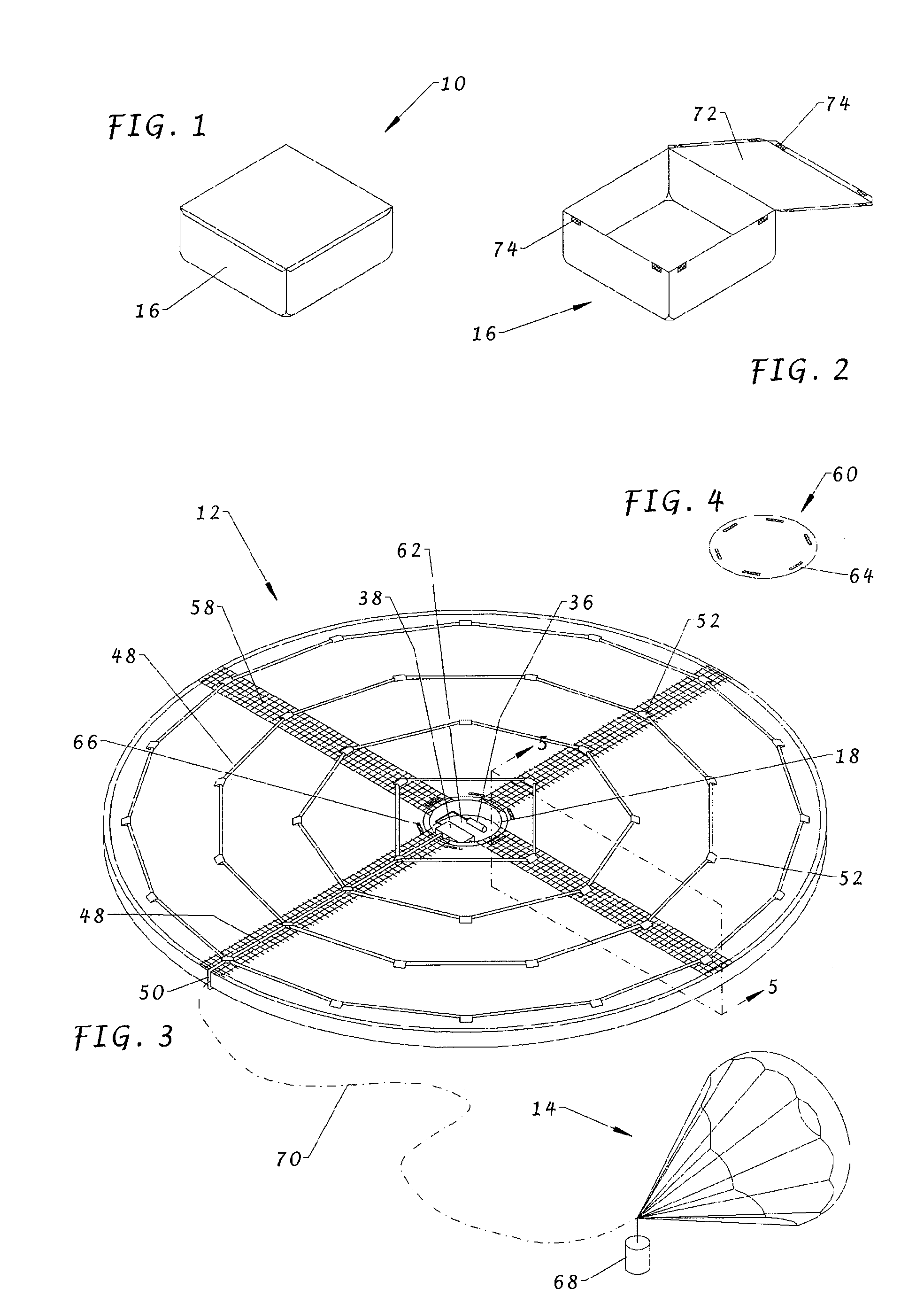
[0019]Referring to the drawings, an inflatable life raft system 10 comprises an inflatable platform 12, a drogue 14 and a bag 16 for the life raft 10. The platform 12, when inflated, has the shape of a circular disc having a diameter of, for example, 3 m and a thickness of, for example, 50 mm. The center of the platform 12 is formed with a circular opening 18 having a diameter of for example, 300 mm. The platform 12 may, of course, be made in other sizes.

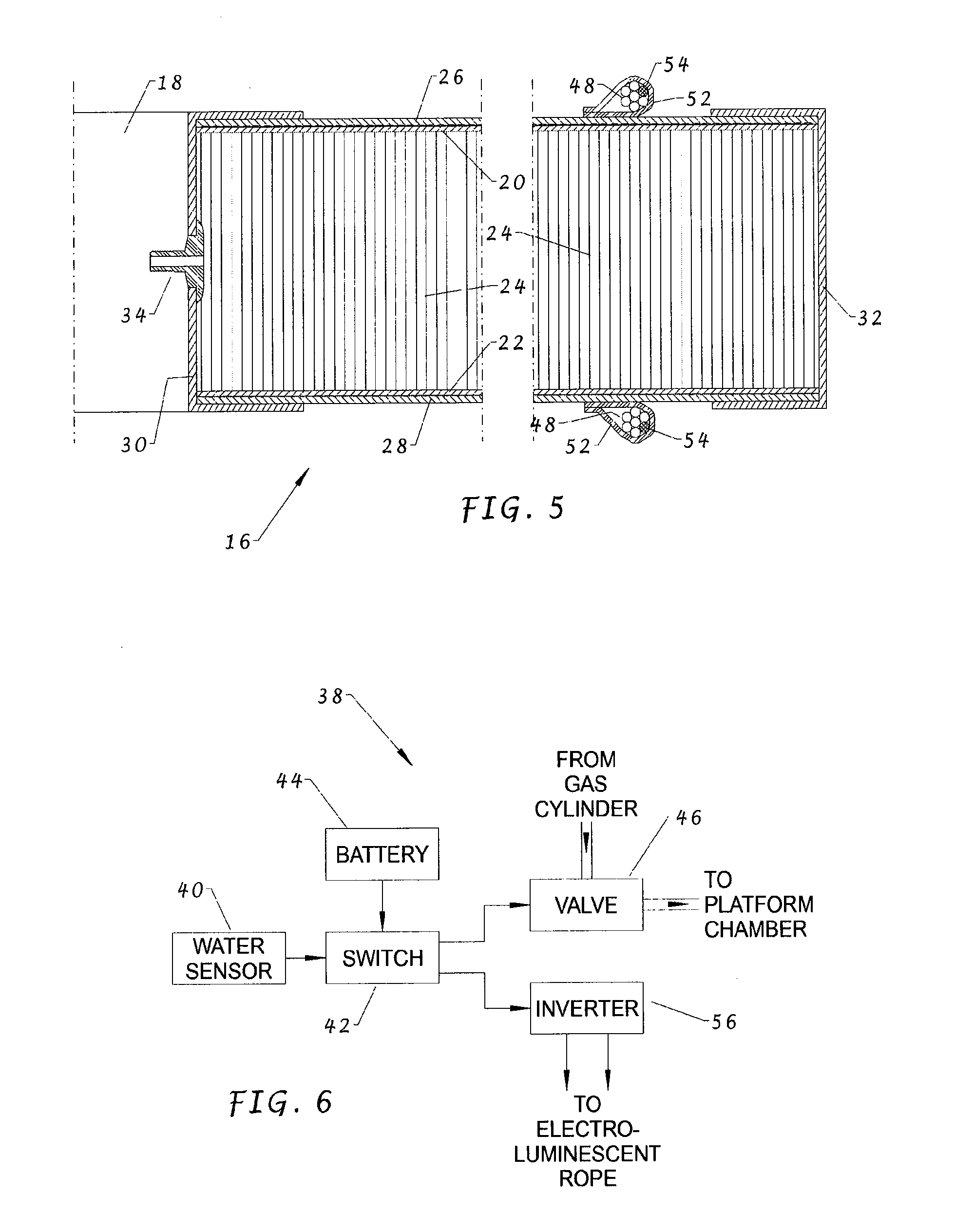
[0020]Referring in particular to FIG. 5, the platform 12 is constructed of two layers of fabric 20, 22 which are joined together by a large number of threads 24 using the “drop thread” method which is well-known in the field of velvet manufactu...


PUM


Abstract

An inflatable life raft has a platform or platform portion formed by two flexible panels joined together by each of a plurality of threads to limit the distance apart that the panels can be moved, the panels being sealed to each other at their edges to form a chamber. A sensor can detect when the life raft is in the water, and an inflation system is operable in response to such detection to inflate the chamber with a gas. Preferably, the threads have similar lengths so that, when the chamber is inflated, the panels are substantially parallel. Accordingly, it is possible to fabricate an inflatable life raft which does not balloon out and which can provide a substantially flat platform.

Description

CROSS REFERENCE TO RELATED APPLICATIONS[0001]This is a U.S. national phase filing under 35 U.S.C. §371 of PCT / GB2009 / 051552, filed on Nov. 17, 2009, and entitled “Inflatable Life Raft”, and hereby incorporated by reference.FIELD OF THE INVENTION[0002]This invention relates to inflatable life rafts.BACKGROUD OF THE INVENTION[0003]Life rafts which are inflatable have the advantage that when deflated they take up little storage space. However, a problem is that, when inflated, the inflation chamber tends to balloon out.SUMMARY OF THE INVENTION[0004]In accordance with the present invention, there is provided an inflatable life raft comprising: a platform or platform portion formed by two flexible panels joined together by each of a plurality of threads to limit the distance apart that the panels can be moved, the panels being sealed to each other at their edges to form a chamber; detecting means for detecting an indication that the life raft is in the water; and inflating means operable...

Claims


Application Information

Patent Timeline
Patent Type & Authority Applications(United States)
IPC IPC(8): B63C9/04
CPCB63B45/04B63B2201/04B63C2009/042B63C2009/0041B63C9/04B63B7/08
Inventor RAWLINGS-LLOYD, CONRAD MICHAEL
Owner RAWLINGS LLOYD CONRAD MICHAEL
Why Eureka
Try Eureka