Methods and systems for engine control

Active Publication Date: 2012-01-12
FORD GLOBAL TECH LLC
View PDF9 Cites 53 Cited by
  • Summary
  • Abstract
  • Description
  • Claims
  • Application Information

AI Technical Summary

Benefits of technology

[0003]Vehicles have been developed to perform an idle-stop when idle-stop conditions are met and then automatically restart the engine whe

Problems solved by technology

However, the inventors have recognized a potential issue with such approaches.
While the various approaches may improve torque mitigation during an engine restart, they may also result in reduced driveline torque.
Consequently, in response to an accelerator peda

Method used


Image

  • Methods and systems for engine control
  • Methods and systems for engine control
  • Methods and systems for engine control

Examples


Embodiment Construction

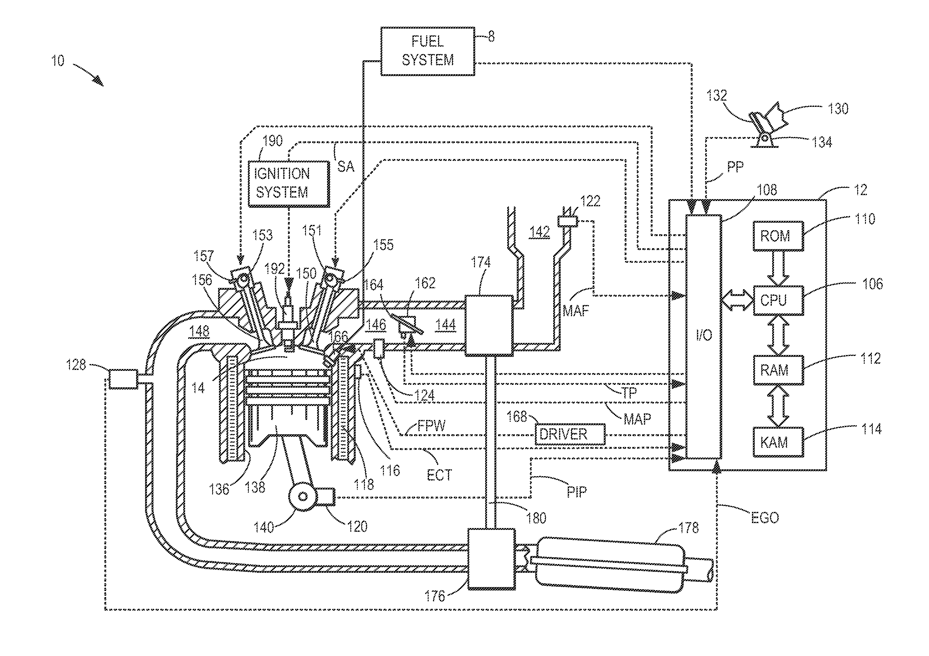
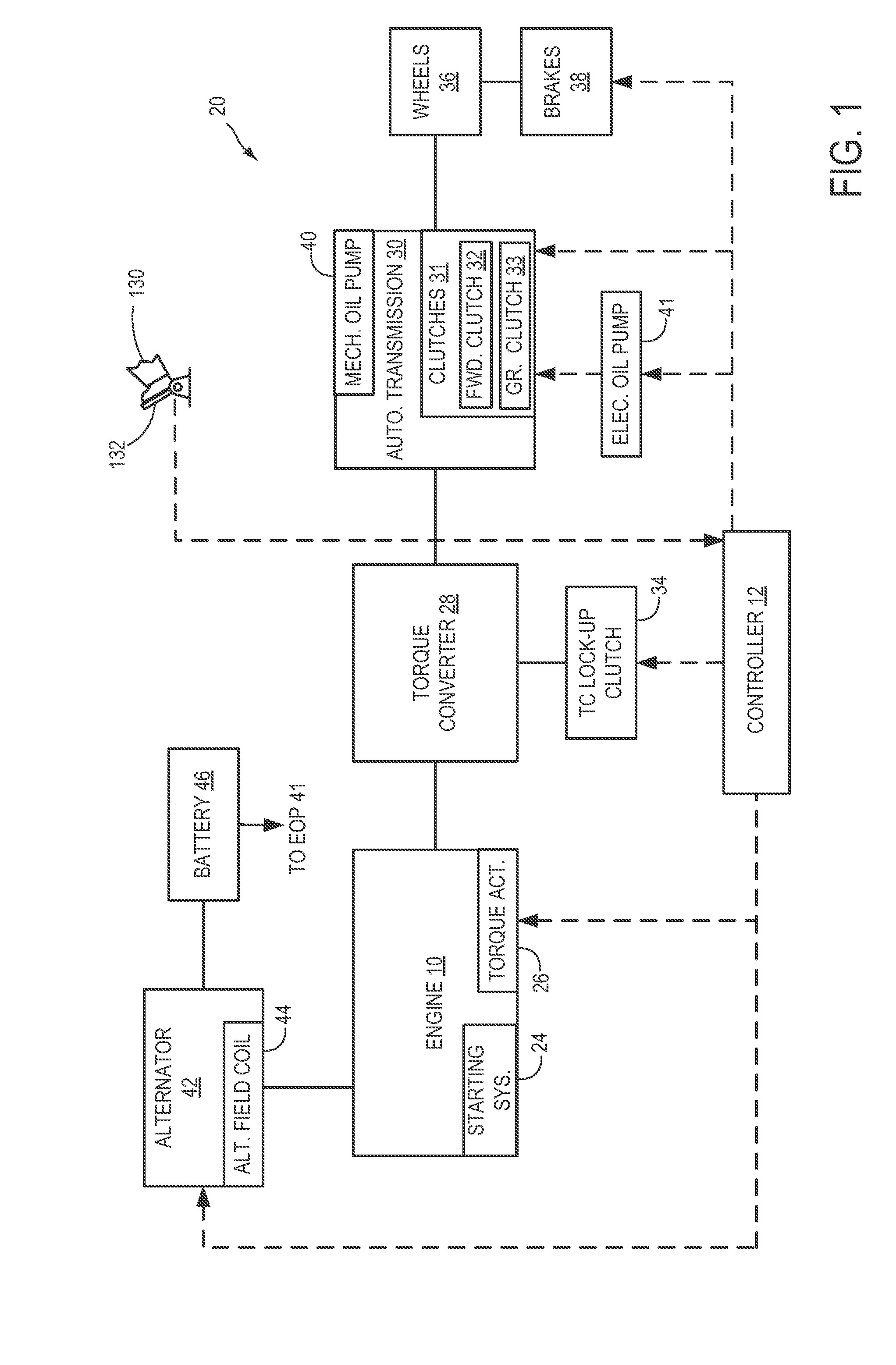
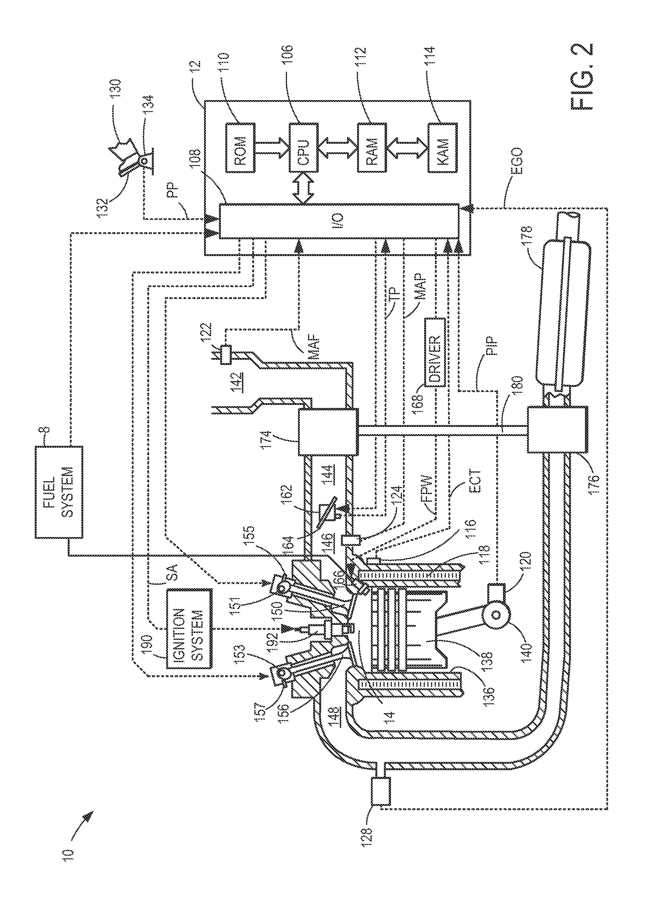
[0016]The following description relates to systems and methods for controlling a vehicle engine system that is selectively deactivatable in response to idle-stop conditions (such as the engine system of FIGS. 1-2). The engine system may be coupled to a transmission. During automatic engine restart conditions, an amount of torque conveyed from the rotating engine to the vehicle wheels is reduced over an interval of the restart to reduce the effects of an engine restart speed spike (FIG. 5). In response to a vehicle launch request from the operator, the torque reduction may be decreased to expedite the return of driveline torque. An engine controller may be configured to perform control routines, such as those depicted in FIGS. 3-4, to shutdown the engine during idle-stop conditions with the transmission shifted to a higher gear, and restart the engine with the transmission upshifted during automatic engine restart conditions. In response to an elevated torque demand during the restar...


PUM


Abstract

Systems and methods are provided for restarting an engine that can be selectively deactivated during idle-stop conditions. In one embodiment, the engine is restarted with torque reduction over an interval of the restart, for example, by upshifting the transmission. In response to a vehicle launch request, the torque reduction is decreased, for example, by downshifting the transmission, to expedite return of driveline torque.

Description

CROSS REFERENCE TO RELATED APPLICATIONS[0001]The present application is a continuation-in-part of U.S. patent application Ser. No. 12 / 833,788, entitled “METHOD FOR CONTROLLING AN ENGINE THAT MAY BE AUTOMATICALLY STOPPED,” filed Jul. 9, 2010, the disclosure of which is hereby incorporated by reference.FIELD[0002]The present application relates to methods and systems for controlling an engine shut-down responsive to idle-stop conditions, and a subsequent engine restart from the idle-stop.BACKGROUND AND SUMMARY[0003]Vehicles have been developed to perform an idle-stop when idle-stop conditions are met and then automatically restart the engine when restart conditions are met. Such idle-stop systems enable fuel savings, reduction in exhaust emissions, reduction in noise, and the like.[0004]A number of approaches have been developed to control the torque relayed between the engine and the wheels of the vehicle during idle-stops and subsequent restarts. For example, the torque conveyed may...

Claims


Application Information

Patent Timeline
IPC IPC(8): B60W10/06B60W30/18B60W10/10
CPCB60W10/06Y10T477/644B60W30/18018B60W30/18027B60W30/1882B60W2510/0638B60W2540/10B60W2710/0644B60W2710/0666B60W2710/1005B60W2710/1061B60W10/02F02N11/00Y10T477/6418Y10T477/675B60W10/11
Inventor NEDOREZOV, FELIXJIANG, HONGGIBSON, ALEX O'CONNOR
Owner FORD GLOBAL TECH LLC
Why Eureka
Try Eureka