
Mechanism to Divert an IP Flow Over a Non-IP Transport

a technology of ip flow and non-ip transport, applied in the field of communication networks, can solve the problems of insufficient bandwidth in the 1p docsis transport to support the number of viewers, first mile, and approach incur considerable cost, so as to facilitate media clients, reduce the cost of migrating, and facilitate the effect of media clients

Inactive Publication Date: 2012-01-12
RPX CLEARINGHOUSE
View PDF10 Cites 3 Cited by
  • Summary
  • Abstract
  • Description
  • Claims
  • Application Information

AI Technical Summary

Benefits of technology

"The present invention provides a method for establishing a communications link between a client and a remote server via a receiving interworking unit and a transmitting interworking unit operable to forward communications between the client and server. The method allows for the efficient transport of unicast content over a network while utilizing existing infrastructure and reducing costs. The invention also allows for more efficient transport of MPEG data and flexible solutions for cable operators as they move from delivering all Entertainment Video as QAM broadcast to delivering it as personalized unicast streams."

Problems solved by technology

The movement from broadcast to “personalized” unicast is coming, but there is insufficient bandwidth in the 1P DOCSIS transport to support the number of viewers that is currently supported by broadcast.
This approach incurs considerable cost in the First Mile, for example by increasing the IP capacity of Data Over Cable Service Interface Specification (DOCSIS) with node splitting and channel bonding a 1a DOCSIS 3.0, or by overbuilding with a FTTH (Fibre to the Home) solution.
Such approaches result in extra costs due to server duplication and change out of clients.

Method used


Image

  • Mechanism to Divert an IP Flow Over a Non-IP Transport
  • Mechanism to Divert an IP Flow Over a Non-IP Transport
  • Mechanism to Divert an IP Flow Over a Non-IP Transport

Examples


Embodiment Construction

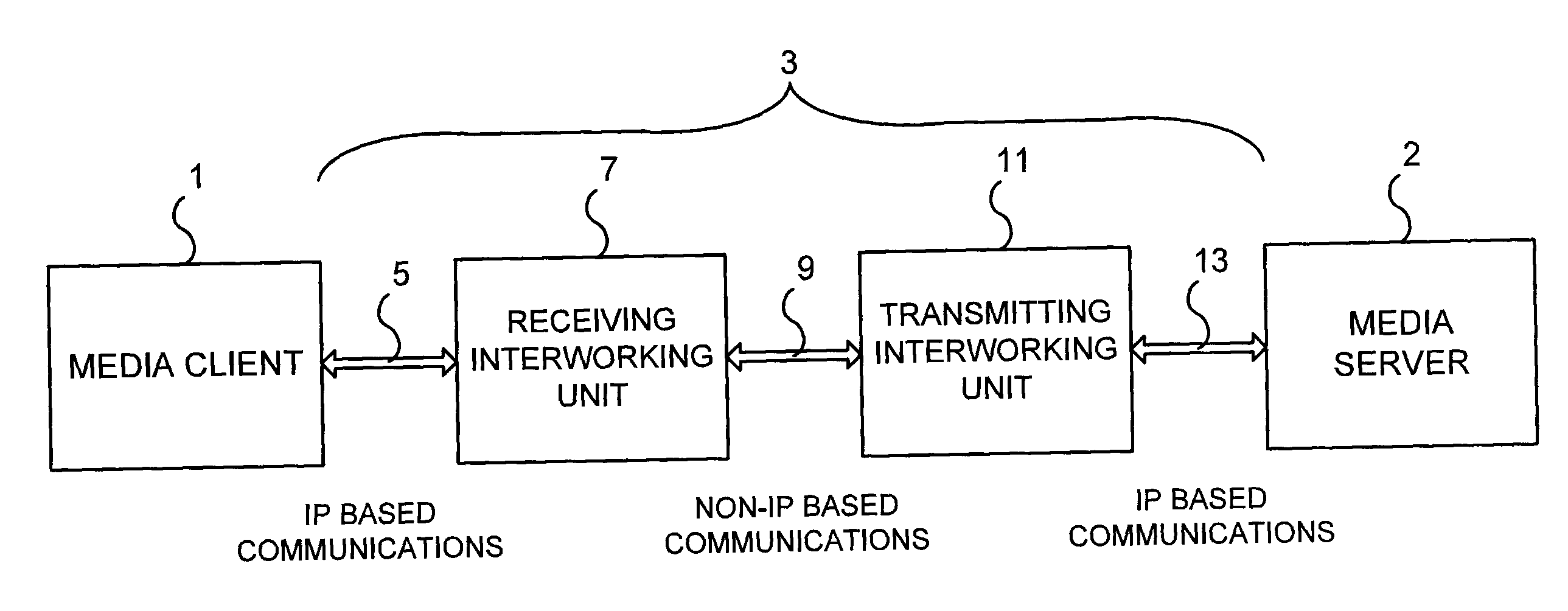
[0018]FIG. 1 is a schematic block diagram of a communications network in accordance with an embodiment of the present invention. Referring to FIG. 1, a media client 1 is connected to a media server 2 via a communications network 3. The media server 2 could be a media gateway (MG), and a media gateway control function (MGCF) and the network addresses of the signaling endpoints (the Control Point) and the MGCF need not be the same as the network addresses of the source and destination of the media stream.

[0019]Typically, the media client 1 will comprise a set-top box (STB) connected to a rendering device. When MPEG media streams are transported to the media client 1, the MPEG media streams are decrypted and decoded and then rendered over an interface such as a High-Definition Multimedia Interface (HDMI) to be displayed on a digital TV. In addition to providing this decryption and decoding function, the media client 1 also is a control point that signals to the media server 2 via the c...


PUM


Abstract

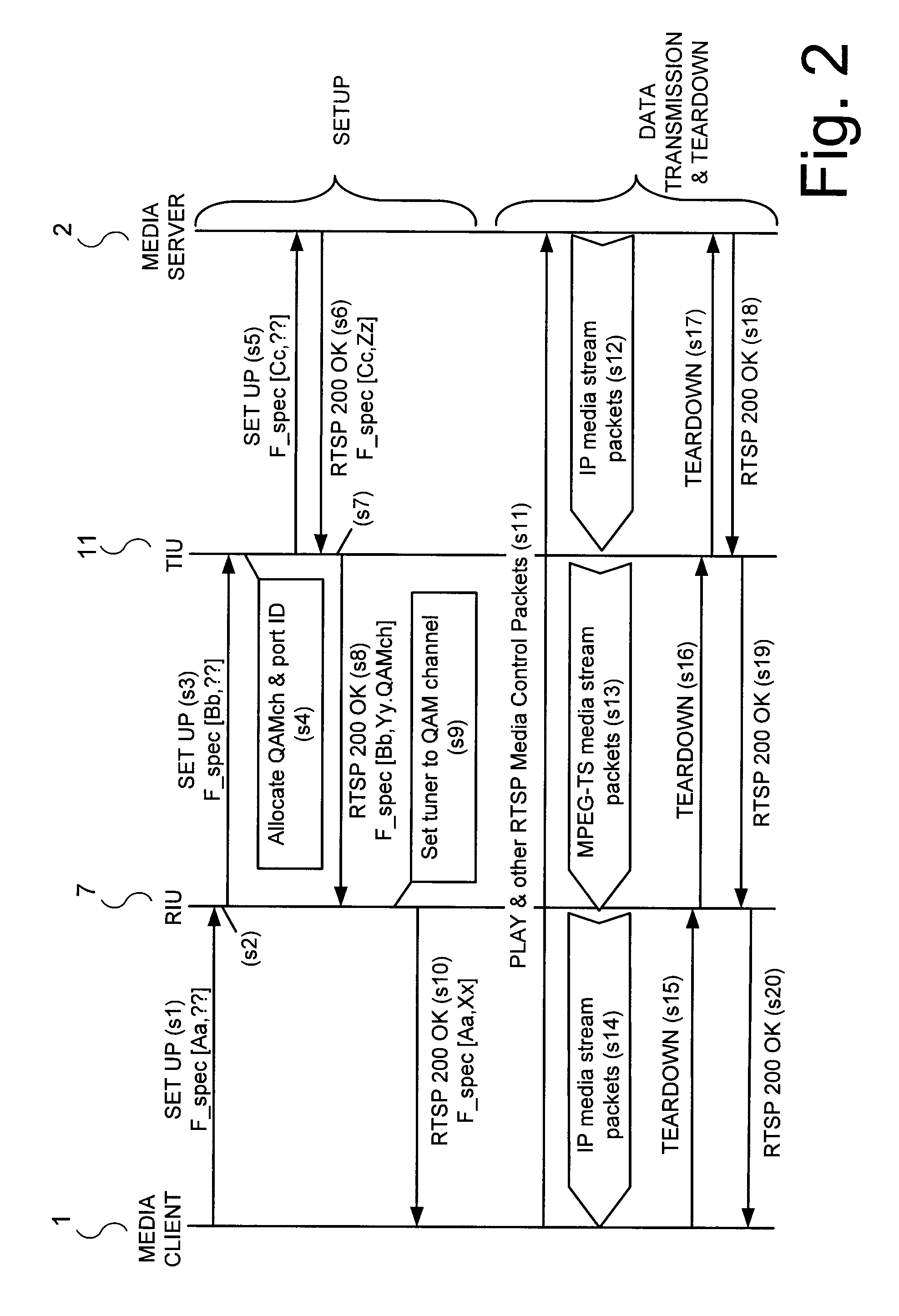
Session flows between a client (1) and a server (2) are pinned through a receiving interworking unit (7) and a transmitting interworking unit (11) connected via the non-IP based communications path (9). The receiving interworking unit (7) and transmitting interworking unit (11) are then configured to convert received data between IP and a non-IP based communications protocols. Subsequently, when the transmitting interworking unit (11) receives IP protocol based data for the client (1) from the server (2) the data is converted and transmitted via the non-IP based communications link to the receiving interworking unit (7). Upon receipt, the receiving interworking unit (7) converts the data back into an IP-protocol based format and forwards the converted data on to the client (1). The disclosed approach enables the client (1), to receive a regular IP packet stream from the server (2), where: one segment (9) of the path between server (2) and client (1) transports the data in a non-IP format; and neither IP client (1) nor the server (2) is aware of the non IP segment and no change in their all IP network mode of operation is required.

Description

TECHNICAL FIELD[0001]The present application relates to communications networks. More specifically the present application concerns methods and systems for transmitting data via a hybrid network where different portions of the network transmit data using different data transmissions protocols.BACKGROUND OF INVENTION[0002]Traditionally the transport of media streams between a server and client has been assumed to be over links with a single homogeneous transport layer e.g. all RTP over IP (Real-time Transport Protocol over IP), all TDM (Time-Division Multiplexing) or all MPEG-TS (MPEG transport stream).[0003]Cable companies now wish to change from MPEG-TS servers and clients to IP servers and clients. The motivation for the transfer from MPEG-TS servers and clients to IP servers arises due to the desire for Video Entertainment delivery to move from a conventional broadcast structure to a personalized unicast structure. At present in a typical Cable TV network, the distribution of dig...

Claims


Application Information

Patent Timeline
Patent Type & Authority Applications(United States)
IPC IPC(8): G06F15/16H04N7/24
CPCH04N21/4363H04N21/64322H04L65/103H04N21/6587H04L65/4076H04N21/64707H04L65/611
Inventor CASEY, LIAM
Owner RPX CLEARINGHOUSE
Learn More